Networks Training

  • About
  • My Books
  • SUGGESTED TRAINING
  • HOME
  • Cisco Networking
    • Cisco General
    • Cisco IOS
    • Cisco VPN
    • Cisco Wireless
  • Cisco ASA
    • Cisco ASA General
    • Cisco ASA Firewall Configuration
  • Certifications Training
    • CCNA Training
    • Cisco Certifications
    • I.T Training
  • General
    • General Networking
    • IP Telephony
    • Network Security
    • Product Reviews
    • Software
  • Cisco Routers
  • Cisco Switches
You are here: Home / Cisco Switches / How to configure a Cisco Layer 3 Switch-InterVLAN Routing Without Router

How to configure a Cisco Layer 3 Switch-InterVLAN Routing Without Router

Written By Harris Andrea

UPDATED: 2020 – Cisco Catalyst switches equipped with the Enhanced Multilayer Image (EMI) can work as Layer 3 devices with full routing capabilities. For example, some switch models that support layer 3 routing are the 3550, 3750, 3560 etc.
layer 3 routing cisco switch

On a Layer3-capable switch, the port interfaces work as Layer 2 access ports by default, but you can also configure them as “Routed Ports” which act as normal router interfaces.

That is, you can assign an IP address directly on the routed port. Moreover, you can configure also a Switch Virtual Interface (SVI) with the “interface vlan” command which acts as a virtual layer 3 interface on the Layer3 switch.

The above feature means that you can implement Layer 3 functionality in your network without using a regular router.

If you don’t have a Layer3 switch available, you can also configure InterVLAN routing using a simple Layer2 switch and a Router (also called Router-on-a-Stick).

Table of Contents

  • Inter VLAN Routing on a Layer 3 Switch
      • Cisco L2 Switches (same configuration for both switches)
      • Cisco Layer 3 Switch
      • Optional ACL Configuration on L3 Switch
      • Important ASA Routing Configuration
  • Inter VLAN Routing on Layer 2 Switches
    • DOWNLOAD ARTICLE ABOVE AS PDF FILE
    • Related Posts

Inter VLAN Routing on a Layer 3 Switch

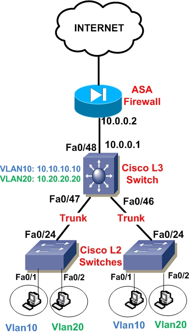
On this post I will describe a scenario with a Layer3 switch acting as “Inter Vlan Routing” device together with two Layer2 switches acting as closet access switches.

Moreover, a Cisco ASA firewall will provide Internet connectivity for all internal subnets. A Routed Port will be configured between the Layer3 Switch and ASA internal interface to route packets towards the internet (via the ASA).

The focus of this article is to show you how to configure the Layer2 and Layer3 switches to provide routing between VLANs using regular IOS based catalyst switches. A similar scenario using the new Cisco Nexus switches is described in the article here.

At the end of this article you will find also important routing configuration commands for the ASA and also how to use Access Control Lists (ACL) on the Layer 3 switch to control traffic (permit or deny) between VLANs at Layer3 level.

This is a fairly popular network scenario that I have seen in many enterprise networks.

See the diagram below to get the whole picture:
MORE READING:  Cisco Switches with Power over Ethernet PoE

Interface Fa0/48 of the Layer3 switch is configured as a Routed Port with IP address 10.0.0.1 and connected to ASA inside interface (10.0.0.2).

Two Vlans need to be created on the L2 and L3 switches, Vlan10 and Vlan20. Of course you can expand this scenario with more Vlans and more Layer 2 switches as needed.

On the Layer3 Switch, for Vlan10 we will create an SVI with IP address 10.10.10.10 and for Vlan20 an SVI with IP address 10.20.20.20. These two IP addresses will serve as the default gateway addresses for hosts belonging to Vlan10 and Vlan20 on the Layer2 switches respectively.

That is, hosts connected to Vlan10 on the closet L2 switches will have as default gateway the IP address 10.10.10.10. Similarly, hosts connected to Vlan20 on the closet switches will have address 10.20.20.20 as their default gateway.

Traffic between Vlan10 and Vlan20 will be routed by the L3 Switch (InterVlan Routing). Also, all interfaces connecting the three switches must be configured as Trunk Ports in order to allow Vlan10 and Vlan20 tagged frames to pass between switches. Let’s see a configuration snapshot for all switches below:

Cisco L2 Switches (same configuration for both switches)

!  Create VLANs 10 and 20 in the switch database
Layer2-Switch# configure terminal
Layer2-Switch(config)# vlan 10
Layer2-Switch(config)# name SALES
Layer2-Switch(config-vlan)# exit

Layer2-Switch(config)# vlan 20
Layer2-Switch(config-vlan)# name ENGINEERING
Layer2-Switch(config-vlan)# exit

!  Assign Port Fe0/1 in VLAN 10
Layer2-Switch(config)# interface fastethernet0/1
Layer2-Switch(config-if)# switchport mode access
Layer2-Switch(config-if)# switchport access vlan 10
Layer2-Switch(config-if)# exit

!  Assign Port Fe0/2 in VLAN 20
Layer2-Switch(config)# interface fastethernet0/2
Layer2-Switch(config-if)# switchport mode access
Layer2-Switch(config-if)# switchport access vlan 20
Layer2-Switch(config-if)# exit

!  Create Trunk Port Fe0/24
Layer2-Switch(config)# interface fastethernet0/24
Layer2-Switch(config-if)# switchport trunk encapsulation dot1q
Layer2-Switch(config-if)# switchport mode trunk
Layer2-Switch(config-if)# exit

Cisco Layer 3 Switch

! Enable Layer 3 routing
Layer3-Switch(config) # ip routing

!  Create VLANs 10 and 20 in the switch database
Layer3-Switch# configure terminal
Layer3-Switch(config)# vlan 10
Layer3-Switch(config)# name SALES
Layer3-Switch(config-vlan)# exit

Layer3-Switch(config)# vlan 20
Layer3-Switch(config)# name ENGINEERING
Layer3-Switch(config-vlan)# exit

!  Configure a Routed Port for connecting to the ASA firewall
Layer3-Switch(config)# interface FastEthernet0/48
Layer3-Switch(config-if)# description To Internet Firewall
Layer3-Switch(config-if)# no switchport
Layer3-Switch(config-if)# ip address 10.0.0.1 255.255.255.252

!  Create Trunk Ports Fe0/47 Fe0/46
Layer3-Switch(config)# interface fastethernet0/47
Layer3-Switch(config-if)# switchport trunk encapsulation dot1q
Layer3-Switch(config-if)# switchport mode trunk
Layer3-Switch(config-if)# exit

Layer3-Switch(config)# interface fastethernet0/46
Layer3-Switch(config-if)# switchport trunk encapsulation dot1q
Layer3-Switch(config-if)# switchport mode trunk
Layer3-Switch(config-if)# exit

MORE READING:  Cisco Show Interface Command on Routers and Switches Explained

!  Configure Switch Vlan Interfaces (SVI)
Layer3-Switch(config)# interface vlan10
Layer3-Switch(config-if)# ip address 10.10.10.10 255.255.255.0
Layer3-Switch(config-if)# no shut

Layer3-Switch(config)# interface vlan20
Layer3-Switch(config-if)# ip address 10.20.20.20 255.255.255.0
Layer3-Switch(config-if)# no shut

!  Configure default route towards ASA firewall
Layer3-Switch(config)# ip route 0.0.0.0 0.0.0.0 10.0.0.2

Optional ACL Configuration on L3 Switch

! Create ACL to control traffic between VLAN 10 to VLAN 20
Layer3-Switch(config)# ip access-list extended ACL1020
Layer3-Switch(config-ext-nacl)#permit ip host 10.10.10.1 host 10.20.20.1
Layer3-Switch(config-ext-nacl)#deny ip 10.10.10.0 0.0.0.255 10.20.20.0 0.0.0.255
Layer3-Switch(config-ext-nacl)#permit ip 10.10.10.0 0.0.0.255 any
Layer3-Switch(config-ext-nacl)#exit

! Apply ACL to VLAN10 SVI
Layer3-Switch(config)#interface vlan 10
Layer3-Switch(config-if)#ip access-group ACL1020 in
Layer3-Switch(config-if)#exit

The configuration above creates an Access Control List to restrict access between Vlan10 to Vlan20. Specifically, it allows host 10.10.10.1 to access only host 10.20.20.1 and denies all other traffic between Vlan10 to Vlan20. Moreover, access to anything else (i.e Internet) from vlan10 is allowed. The ACL above is applied on vlan10 SVI in the “in” direction.

Important ASA Routing Configuration

ASA(config)# route outside 0.0.0.0 0.0.0.0 2.2.2.2  <– This is default route towards internet
ASA(config)# route inside 10.10.10.0 255.255.255.0 10.0.0.1 <– static route to reach vlan10
ASA(config)# route inside 10.20.20.0 255.255.255.0 10.0.0.1 <– static route to reach vlan20

The above ASA sample configuration shows the necessary static routing required on the ASA to route packets back to vlan10 (10.10.10.0) and vlan20 (10.20.20.0) via IP 10.0.0.1 which is the Layer3 switch IP.

Inter VLAN Routing on Layer 2 Switches

People ask me the question if you can route traffic between VLANs on Layer 2 switches. The answer is NO. If there is no routing device in the network (Layer 3 switch or Router) then hosts connected to two different VLANs on the same Layer 2 switch will not be able to communicate.

The only way to provide inter vlan routing on a Layer 2 switch is to have a Layer 3 switch or Router in the network which will receive the packets for each Layer2 VLAN and then route them to the other VLAN accordingly.

See also my other article about a Layer 2 / Layer 3 Switch Design and Configuration example with aggregation and access switches and Port Channels for link redundancy.

DOWNLOAD ARTICLE ABOVE AS PDF FILE

Related Posts

  • How to Configure a Loopback Interface on Cisco Router & Switch
  • Cisco Switch Layer2 Layer3 Design and Configuration
  • Description of Switchport Mode Access vs Trunk Modes on Cisco Switches
  • What is an SFP Port-Module in Network Switches and Devices
  • 8 Different Types of VLANs in TCP/IP Networks

Filed Under: Cisco Switches

Download Free Cisco Commands Cheat Sheets

Enter your Email below to Download our Free Cisco Commands Cheat Sheets for Routers, Switches and ASA Firewalls.

We use Elastic Email as our marketing automation service. By submitting this form, you agree that the information you provide will be transferred to Elastic Email for processing in accordance with their Terms of Use and Privacy Policy. Also, you allow me to send you informational and marketing emails from time-to-time.

About Harris Andrea

Harris Andrea is an Engineer with more than two decades of professional experience in the fields of TCP/IP Networks, Information Security and I.T. Over the years he has acquired several professional certifications such as CCNA, CCNP, CEH, ECSA etc.

He is a self-published author of two books ("Cisco ASA Firewall Fundamentals" and "Cisco VPN Configuration Guide") which are available at Amazon and on this website as well.

Comments

  1. Walt says

    October 17, 2009 at 4:09 am

    Great article

  2. patice says

    October 17, 2009 at 5:12 pm

    Well done mate, well explained…..Thanks

  3. Unes says

    November 3, 2009 at 10:44 pm

    thanks for this article , but i have some questions

    in fact in this scenario the security access-lists will be performed on the layer 3 switch rather than the firewall right ?
    2- what if i have a DMZ segment and i want grand access from DMZ to VLAN 10 ( servers VLAN )
    3- if i wan’t a VPN remote access tunnel from internet to VLAN 10 how can i configure the routing ?

  4. BlogAdmin says

    November 4, 2009 at 2:05 am

    1) The layer 3 switch can have security access-lists for controlling traffic ONLY between the VLANs (e.g traffic from Vlan10 to Vlan20 and vica-versa). This is usually useful for providing internal LAN segmentation and traffic control.
    2) If you have a DMZ on the firewall and want to grant access to vlan10, you need to allow this traffic on the ASA access-list and also configure the proper static nat on the ASA to allow access from lower security level (DMZ) to higher security level (vlan10). Note that vlan10 is still considered as inside zone (higher security level) for the ASA. The ASA also must have a static route pointing to internal vlan10 (route inside 10.10.10.0 255.255.255.0 10.0.0.1)
    3) As explained above, you need to configure a static route on the ASA to be able to reach the vlan10 network. The Layer3 switch needs only to have a default route pointing to the ASA 10.0.0.2 .

  5. bonez says

    March 2, 2010 at 11:57 pm

    Is it possible to communicate between two VLAN in different LAYER 3 switch and the same subnetwork.

  6. BlogAdmin says

    March 3, 2010 at 1:35 am

    bonez,
    No, you can not have the same subnetwork spanning a Layer3 boundary. Once you introduce a Layer3 in your path, the subnetworks MUST be different. However, a Layer3 switch can work as Layer2 as well or a combination. If the VLAN you mention is pure Layer2 Vlan (i.e you have not configured an “Interface Vlan xxx”) then you can have hosts belonging in the same subnetwork and connected on two different switches (in the same Layer2 Vlan).

    Please let me know if I’m not clear.

  7. bonez says

    March 4, 2010 at 1:18 am

    thank you sir.

  8. nelson says

    April 20, 2010 at 7:21 am

    On the inside interface of the ASA Ethernet0/1 the ip address should be 10.0.0.2 right?

  9. Blog Admin says

    April 20, 2010 at 3:24 pm

    Yes this is correct. This means also that the Cisco Layer3 switch should have a default route pointing to 10.0.0.2

    ip route 0.0.0.0 0.0.0.0 10.0.0.2

  10. nelson says

    April 20, 2010 at 5:10 pm

    Thanks a lot. I am going to try it tonight. So what is the ip address of the l3 switch? I mean if I want to telnet to the switch from Vlan10.

  11. Blog Admin says

    April 20, 2010 at 6:37 pm

    The IP of the switch if you are in Vlan 10 is 10.10.10.10. So if you telnet to that address it should work

  12. nelson says

    April 20, 2010 at 9:16 pm

    Just a few more question:
    1. In order to telnet to the l2 switches do I need to create VSI like:
    layer2-switch (config)#interface vlan10
    layer2-switch(config)#ip address 10.10.10.11 255.255.255.0
    layer2-switch(config)no shut

    2. If I put another cisco l3 switch (c3550), would I use the same configuration of the l2 switch?

    Regards,
    Nelson

  13. Blog Admin says

    April 21, 2010 at 11:53 am

    Nelson,

    For your first question: Normally for a Layer2 switch you use Vlan1 for management. So you configure an IP address under Vlan1

    interface vlan1
    ip address 192.168.1.1 255.255.255.0

    However, you will need to have a management station in a Vlan1 port in order to telnet to the switch at 192.168.1.1. The other alternative is that you can configure Vlan10 lets say as a management Vlan and then configure an IP address in Vlan10 subnet space (e.g 10.10.10.11 as you describe above). However, only from PCs connected to Vlan10 ports will be able to Telnet to the switch. Also, you should shut down Vlan1 if you configure a Vlan10 SVI.

    For you second question I did not understand what you want to achieve exactly. Can you please elaborate?

  14. nelson says

    April 21, 2010 at 12:20 pm

    Thanks for the advise. I able to created the intervlan except for get into the internet. I tried to ping the inside interface of ASA 10.0.0.2 but it not goes through. Can you help me with this?

  15. Blog Admin says

    April 21, 2010 at 1:49 pm

    ASA should have the proper routing for 10.10.10.0 and 10.20.20.0 networks. You must configure a static route on ASA as following:

    route inside 10.10.10.0 255.255.255.0 10.0.0.1
    route inside 10.20.20.0 255.255.255.0 10.0.0.1

  16. nelson says

    April 22, 2010 at 6:08 am

    It worked. Thank you very much for your help.
    Nelson

  17. mon says

    May 28, 2010 at 5:00 pm

    hi, i have 2 x 3750E switches connected via the gi1/0/25 interfaces as trunks. how do i enable the ip routing? the command “ip routing” is invalid.
    thanks in advance…

  18. Blog Admin says

    May 28, 2010 at 6:38 pm

    Hello Mon,

    By default, IP routing should be already enabled on the 3750E. See the following from Cisco site:

    The Cisco Catalyst 3750-E Series is orderable with two feature sets:

    * IP Base: Includes advanced quality of service (QoS), security, and basic routing functionality
    * IP Services: Also includes advanced hardware-based IP unicast and multicast routing, as well as Virtual Route Forwarding (VRF), and policy-based routing (PBR).

    Therefore if you configure SVI interfaces (interface Vlan x) and configure an IP address on the SVI you should be able to implement Layer3 routing on the switch.

    Let me know if you need any help on that.

    Harris

  19. Den Askbow says

    September 16, 2010 at 9:12 am

    Hi. Thanks for the post!
    A little question:
    what the Layer3-Switch(config-if)# no switchport
    command actually does and why we need one?
    Could we create just another vlan, set the helper-address on vlans 10-20 to point to the ASA for it to work as dhcp?

  20. Blog Admin says

    September 17, 2010 at 7:06 pm

    The command “no switchport” configures the specific interface as a Layer 3 routed interface. On a layer3 switch, interfaces can be configured in different modes of operation, such as pure layer 2 (switchport), pure layer3 (no switchport), trunk port etc.

  21. DMB says

    November 22, 2010 at 6:13 am

    hi? i have elementary question?
    How can u create encapsulation dot1q on layer 2 switch, i tried it but it didn’t work.

  22. Blog Admin says

    November 22, 2010 at 7:31 am

    Hi there,

    If the switch is one of the newest models (e.g 2960 etc) the encapsulation dot1q is the default option (and the only option) so you don’t have to configure it. Just configure the port as a trunk port and thats it.

  23. michael Chisina says

    November 23, 2010 at 6:22 pm

    What configs setting can you put on a 2611 router as a firewall instead of Cisco ASA firewall:
    regards

  24. Blog Admin says

    November 24, 2010 at 9:15 am

    A Cisco IOS Router can work as a firewall as well. It is called Cisco IOS Firewall or CBAC (Context Based Access Control). You should get a specific IOS software image version which supports this functionality. Basically you use “ip inspect” commands to apply inspection for certain protocols and also using dynamic access lists. Do a search on Cisco website about CBAC for more information.

  25. satya says

    November 30, 2010 at 6:16 pm

    VERY NICE DOCUMENT FOR EVERY END USER

    THX

  26. Todd says

    December 4, 2010 at 3:36 am

    Im doing router on a stick with 2950 and 1721. I have the 1721 connected to a home linksys WRT54GL. Lsys=192.168.1.1 — 1721 =192.168.1.2 . R.O.S. is 10.100.20 / .30 and so on. 1721 has DNS entry of my ISP. I can ping google from 1721 but not from switch. from pc on vlan 20 I can ping 10.100.20.254 or 30.254 (DG’s) and 192.168.1.2 but not 192.168.1.1 or Google.

  27. Blog Admin says

    December 4, 2010 at 10:48 am

    Todd,

    The problem seems to be on the Linksys. It does not have the proper static routes to reach the ROS subnets (10.100.20 etc). You must configure static routes on Linksys to reach 10.100.20 /.30 subnets via gateway 192.168.1.2 (which is the 1721 router).

  28. todd says

    December 4, 2010 at 7:36 pm

    Thanks, I was hoping to make this for someone who wouldnt have to touch the Linksys and be plug and play. I will use this to examine config options on the cisco side.

  29. Zonko says

    January 13, 2011 at 8:30 pm

    Excellent article.

    If I wanted to add an additional couple of L2 switches, say for expansion or growth purposes, do I just connect them to the layer 3 switch via trunk ports and then set new vlans on the L2 switches?

  30. Blog Admin says

    January 15, 2011 at 1:06 pm

    Yes, you can do it like you said.

  31. Elegua says

    February 5, 2011 at 10:45 pm

    Very nice article.

    I have a question, in this case you have only one link between the L3 switch and the ASA and default route its fine, how would you do it in case you have two ASAs pointing to a two different ISPs but you want that users in all vlans use both links,ex: one link is internet and the other is a MPLS to a remote location, all user need access to both locations, when they require access to internet use the internet link, when they require access to a database or any service in the remote location using the MPLS link?, its that possible without using any routing protocol?, can i use static routes base in destination IP address?

    MPLS : 10.10.10.0/29
    Internet: 20.20.20.0/29

    ex:
    ip route 10.10.10.0 255.255.255.248 interface 0/23 Inte

    ip route 20.20.20.0 255.255.255.248 interface 0/24 MPLS

    Thanks in advance.

  32. Blog Admin says

    February 6, 2011 at 8:05 am

    Elegua,

    Yes, this is the way to do it. However, instead of pointing the static route to an outgoing interface, I would use the internal IP address of the proper ASA. Also, for the internet, you must use a default static route.

    e.g

    ip route 0.0.0.0 0.0.0.0 10.0.0.2
    ip route 20.20.20.0 255.255.255.248 10.1.1.2

    (10.0.0.2 = IP address of ASA connecting to internet)
    (10.1.1.2 = IP address of ASA connecting to MPLS network)

  33. edgard says

    February 9, 2011 at 6:44 am

    My problem is that I can not config a ip address on the ASA interface e0/1. its say that this command is just for Vlan interfaces. Any ideas? I even did no ip default gateway. my asa is the dhcp server. ASA 5505 basic license. I hope i dont have to have security plus license for the ASA.

    Thanks for you help

  34. Blog Admin says

    February 9, 2011 at 11:52 am

    Edgard,

    On ASA 5505 models, all interfaces are Layer2 interfaces which belong to a certain Vlan (Vlan 1 for ports 1 to 7 and Vlan 2 for port 0). So you assign the IP address to the “interface Vlan 1” command.

  35. Steve says

    February 9, 2011 at 2:46 pm

    I think you’ve made an error in response 4 above, which I’ve found is a common misconception regarding L3 switches. You cannot apply standard layer 3 ACL’s to control inter-vlan routing in your scenario. Traffic entering the L3 switch on a trunk port are already members of the vlan they are tagged with. Therefore inbound ACL’s do not apply to that traffic. You must use the more complicated Cisco’s VLAN MAPs in this instance to secure traffic from one vlan to another within the switch. If you don’t take this step, then all traffic can travel between vlans unrestricted, so what’s the point in segmenting to begin with? It’s a subtle point, but not trivial with Cisco L3 switches.

  36. Blog Admin says

    February 9, 2011 at 7:05 pm

    Steve,

    Using layer3 access lists to control traffic between vlans on a Layer3 switch is something that I have done several times in the past. Basically the ACL is applied on the SVI interface in the “in” direction to control which traffic can exit this specific vlan for other vlans as destination. This is something that I have simulated also a few minutes ago on my Cisco packet tracer and works fine. As I have said, traffic within the same vlan is not affected by the ACL, but traffic between vlans is controlled by the ACL.

  37. edgard says

    February 10, 2011 at 1:17 am

    So 10.0.0.2 should be my interface ip address that will be my route set up to pass traffic?

    “On the inside interface of the ASA Ethernet0/1 the ip address should be 10.0.0.2 right?”

    and route 0.0.0.0 0.0.0.0 10.0.0.2

    on the asa I need to create the route also?

    route inside 10.10.10.0 255.255.255.0 10.0.0.1
    route inside 10.20.20.0 255.255.255.0 10.0.0.1

  38. Blog Admin says

    February 10, 2011 at 6:33 pm

    Yes, thats correct. However, if the ASA is model 5505, the IP address 10.0.0.2 must be assigned to interface vlan 1.

  39. edgard says

    February 11, 2011 at 5:43 pm

    I have another question. I have another scenario, if i have two vlan on the on the L3 Switch and I connect two interfaces to form the 3550 to the ASA 0/1 and 0/2, been 0/1 for vlan 1 on the asa and 0/2 for the dmz vlan, this will be to segment the network no just in the LAN but also in the asa. its that possible? and if its what should be the better way to configured this scenario? my big problem should be the loops. any suggestions on this one?

    Thank you very much for your help.

  40. edgard says

    February 14, 2011 at 7:00 am

    I did the config as you explain before with the vlan ip as 10.0.0.2 for vlan1 inside but i have no ip address on host for SVI as should have it for that vlan3.
    The ASA is running on router firewall mode and running DHCP with scope 192.168.1.100 – 192.168.1.200.
    ping from switch and asa are reply from vlan1 inside to vlan3 on the switch.
    what colud be the problem? I’m using Polycom for the IPphones on the vlan3 and they get the configuration from outside server on the cloud, I think this could be a DHCP issue since IPPhones can not get ip even when they are on switchport access and switchport access vlan 3.

    Int f0/7
    description IP Phone
    switchport access
    switchport access vlan 3

    L3 switch:
    interface Vlan3
    ip address 192.168.3.1 255.255.255.0

    int f0/3
    description link to asa – router port
    no switchport
    ip address 192.168.1.2 255.255.255.0

    route 0.0.0.0 0.0.0.0 192.168.1.1 (Vlan1 on asa)

    ASA 5505:
    route inside 192.168.3.0 255.255.255.0 192.168.1.2
    route outside 0.0.0.0 0.0.0.0 x.x.x.x (outside ip internet)

    Thanks again.

  41. Rich says

    February 14, 2011 at 6:41 pm

    What if we dont want ACLs on the Layer3 switch, we want all that on the ASA only. What would the config look like?

  42. Blog Admin says

    February 14, 2011 at 7:32 pm

    Rich,

    The link connecting the switch with ASA must be a trunk port. Then, you configure the ASA physical interface with subinterfaces, with each subinterface being one vlan coming from the switch. Only Layer2 vlans must be configured on the switches without any layer 3.

  43. edgard says

    February 14, 2011 at 8:15 pm

    Any Ideas on this one? it may be the DHCP that is not giving ips? how we setup the dhcp server from the L3, on mine I have it from the asa but hosts are not getting ip.

    Int f0/7
    description IP Phone
    switchport access
    switchport access vlan 3

    L3 switch:
    interface Vlan3
    ip address 192.168.3.1 255.255.255.0

    int f0/3
    description link to asa – router port
    no switchport
    ip address 192.168.1.2 255.255.255.0

    route 0.0.0.0 0.0.0.0 192.168.1.1 (Vlan1 on asa)

    ASA 5505:
    route inside 192.168.3.0 255.255.255.0 192.168.1.2
    route outside 0.0.0.0 0.0.0.0 x.x.x.x (outside ip internet)

    Thanks again.

  44. Blog Admin says

    February 16, 2011 at 3:09 pm

    edgard,

    you confused me big time. Anyway, I believe the issue is that the DHCP server is not on the same layer3 subnet as the phones (as I understand from your description). You will need to configure DHCP forwarding using ip helper-address. Research this on Google for more information.

  45. edgard says

    February 16, 2011 at 5:13 pm

    Im sorry, i’m going to try to be more specific.

    im using the same topology that you have here in your blog. I have Vlan 2 192.168.2.1 – Vlan 3 192.168.3.1. The DHCP Server is running on the ASA with a range of 192.168.1.100 – 200 but as you see the Vlan3 is not in the same subnet as the dhcp, so my question is that when i have f0/7 on switchport access vlan3 for my ipphone the phone get a 10.x.x.x ip and not 192.168.3.x from vlan3.

    Should I have a dhcp disable on the asa?
    Is the vlan 3 acting as dhcp server for that vlan3?
    Do I need a dhcp server for each vlan?

    Int f0/7
    description IP Phone
    switchport access
    switchport access vlan 3

    L3 switch:
    interface Vlan3
    ip address 192.168.3.1 255.255.255.0

    int f0/3
    description link to asa – router port
    no switchport
    ip address 192.168.1.2 255.255.255.0

    route 0.0.0.0 0.0.0.0 192.168.1.1 (Vlan1 on asa)

    ASA 5505:
    route inside 192.168.3.0 255.255.255.0 192.168.1.2
    route outside 0.0.0.0 0.
    0.0.0 x.x.x.x (outside ip internet)

    Thanks and let me know if I can be more specific, thanks.

  46. Blog Admin says

    February 16, 2011 at 5:55 pm

    DHCP is a Layer2 broadcast protocol and therefore can not pass through layer3 borders. You need to use “ip helper-address” command on the layer3 switch in order to transfer the DHCP request from vlan 3 towards the ASA firewall which works as DHCP server.

    see this link for more info:

    https://www.networkstraining.com/forwarding-a-dhcp-request-using-cisco-ip-helper-address-command/

  47. edgard says

    February 16, 2011 at 6:12 pm

    Yes, seems like that was the problem, I was reading about it, I need to test tonight and let you know.

    thanks

  48. edgard says

    February 22, 2011 at 5:28 pm

    I figure out, the problem is that the SVI need not just the ip helper but also a pool of network to work by each vlan. so it will be like this for each vlan you have.

    ip dhcp pool XBOX_NETWORK
  
    network 10.200.70.0 255.255.255.252
    
default-router 10.200.70.1 
  
    dns-server 192.168.1.1 


    !
ip dhcp pool PC_NETWORK
  
    network 10.200.60.0 255.255.255.248
  
    default-router 10.200.60.1 
  
    dns-server 192.168.1.1

    interface Vlan60
    
ip address 10.200.60.1 255.255.255.248


    !
interface Vlan70
    
ip address 10.200.70.1 255.255.255.252
     
    Please let me know if anybody need helps.
    thanks for your help.

  49. soyful says

    February 22, 2011 at 9:25 pm

    Hello,

    Great article. I was able to follow and actually get intervlan routing to work but none of my pcs in the new vlan can connect to the internet. Would appreciate any ideas.

    Here is my setup
    two 3750s and a sonicwall router
    router address 10.0.0.1
    vlan 1 on 3750 10.0.0.180
    vlan 2 on 3750 10.0.2.0

    As mentioned above, pcs can communicate on both networks but pcs from vlan 2 cannot connect to internet. From vlan 2 I can ping the router. The router also has a static route for vlan 2.
    When I tracert from a pc in vlan 2, I get a reply from 10.0.2.1 (vlan 2) destination host unreachable.
    Thanks.

  50. Blog Admin says

    February 23, 2011 at 5:48 am

    Soyful,

    Did you configure a default route on the Layer3 3750 switch. This default route should point to your Sonicwall router:

    Layer3-Switch(config)# ip route 0.0.0.0 0.0.0.0 10.0.0.1

    The Layer3 switch knows how to send packets to your Sonicwall because it is directly attached to it, but it does not know how to send packets to the internet, hence you need the default route.

  51. soyful says

    March 3, 2011 at 10:20 pm

    Thank you. You sir are a genius. That worked.
    Had to wait a some time because of the production environment.

  52. ashish says

    March 8, 2011 at 4:06 pm

    Can I link L3 interface in switch to a subinterface of router directly

  53. Tommy says

    March 8, 2011 at 5:24 pm

    Very nice article,

    I do not have a firewall. Refer to your diagram, let’s say I have an internet connection plugging to the layer 3 switch. How do I configure NAT for VLAN 10 and VLAN 20. I have a cisco layer 3 switch 3560.

  54. Rofhiwa says

    March 12, 2011 at 2:17 pm

    Encapsulation protocol specified must be on top of trunking statement config, bcz sometimes a need you to define encapsulation trunking protocol.

  55. Thomoil Rofhiwa says

    March 12, 2011 at 2:25 pm

    Trunking will accept “switchport mode trunk” only if you execute “switchport trunk encapsulation dot1q” command first.Configurations as follows:-

    switch#conf t
    switch(config)#host SW1
    SW1(config)#inter fa0/47
    SW1(config-if)#switchport trunk encapsulation dot1q
    SW1(config-if)#switchport mode trunk

  56. Blog Admin says

    March 12, 2011 at 6:35 pm

    yeah, thats correct, depends on the switch software IOS version though.

  57. Blog Admin says

    March 12, 2011 at 6:41 pm

    You will need to use the commands “ip nat inside” and “ip nat outside” on the vlan interfaces. Then use the command “ip nat inside source list xxx” to select which traffic will be nated

  58. vsr says

    March 20, 2011 at 6:57 am

    Really good job Admin..
    I am working on a academic project which deals with the vlan and the attacks that are possible on it. During my search I found that most of the vlan attacks are already patched in the CISCO switches and the rest that are still possible can be due to misconfiguration of the vlan or the ACL that we use for it. So can there be still vulnerabilities existing in the vlan security, or all are patched. What can be the state of art of the security of the vlan and the attacks on it?

  59. Blog Admin says

    March 21, 2011 at 7:20 pm

    Layer 2 Vlans provide excellent security, especially from remote attacks. Now, if the attacker has physical access to the switch, there could be also some vlan security issues (e.g on ports configured as trunks etc). Overall, vlan segmentation of subnets is considered good security practice.

  60. Rahul-DG says

    March 28, 2011 at 4:36 pm

    Hi,

    I have a new switch 2960 connected to 1841 Router.
    No DHCP server installed.
    I hv created DHCP service on 2960
    Created switch telnet service on vlan1 — 10.25.19.2 255.255.255.0

    I am being able to have IP leased to my pcs
    can ping default gateway 10.25.19.1
    can ping Printer 10.25.19.3
    ==> unable to ping 10.25.19.2 (telnet Ip) from WAN side
    ==> not a single pc can ping any one
    ==> no internet through .1

    Cld u please help. Thanks a lot in advance.

  61. Rahul-DG says

    March 28, 2011 at 4:48 pm

    ==> pls find my config script.

    # Int vlan 2
    # ip address 10.25.19.2 255.255.255.0
    no shut

    Service dhcp
    ip dhcp pool
    network 10.25.19.0 /24
    dns-server 10.25.19.1
    default-router 10.25.19.1
    lease 7
    domain-name
    exit
    ip dhcp excluded-address 10.25.19.1
    ip dhcp excluded-address 10.25.19.2
    ip dhcp excluded-address 10.25.19.3 [.1 : router / .2 – switch / .3 Printer]
    exit

    Switch(config)# interface range fa0/1 – 24
    Switch(config-if-range)# switchport host

    Any help would be highly appreciated.

  62. Rahul-DG says

    March 28, 2011 at 4:59 pm

    …Few update :

    from Lan –> can ping 10.25.19.1 & .2 & .3

    from WAN side –> can ping .1(GWay) & .3 [but NOT .2]

    No Internet/Intranet connection through .1 (from LAN)

    No pc can ping any other.

    Where is the issue ?

    Thanks a lot in advance.

  63. Nathan says

    March 29, 2011 at 3:55 pm

    Hi,I tryed to do this topology at Packet Trace, but, i can’t set “switchport trunk encapsulation dot1q”. I don’t know why, but, the switch don’t agree this command…

    Do you have any idea for issue it?

    Later I’ll try use another simulator…

    great article!

  64. Blog Admin says

    March 29, 2011 at 4:21 pm

    Nathan,

    Newest IOS versions have the switchport trunk as dot1q by default, so you don’t need to specify this anymore. In the past you had the option to set the trunk to “isl” encapsulation which was Cisco proprietary but is not used anymore.

  65. Blog Admin says

    March 29, 2011 at 4:26 pm

    Rahul
    too much and confusing information. Be more clear. How is the exact topology? what do you want to achieve?

  66. Nathan says

    March 29, 2011 at 4:48 pm

    well, i just need to set “switchport mode trunk native” then(?), because I get two options…native and allowed.

    PS: I’m starting now at ciscos worlds, so, my question could be not make sense xD

  67. Blog Admin says

    March 29, 2011 at 6:28 pm

    You don’t need to configure native. Just do the following:

    “switchport mode trunk”

    and thats it.

  68. Rahul-DG says

    March 30, 2011 at 6:21 am

    Blog, I want all the dhcp leased host to browse Internet

    GWay is connected to the switch
    Switch is leasing the IPs to the host
    Host can ping GW
    Printer can be pinged through the gateway
    I want Hosts to browse Internet

    Thanks

  69. Rahul-DG says

    March 30, 2011 at 6:44 am

    Blog …this is the pic

    Internetgateway (ROUTER) connected to the backbone VPN network and is up. this is WAN side

    LAN side : I don’t have any DHCP server

    One switch 2960 connected to the above ROUTER/GW and all the computers and printer are connected to the SWITCH.

    configured DHCP on the SWITCH and is leasing IP.

    Can PING GW from the host

    but no internet connection thru the GW to the backbone network/VPN

    I hv shared the script above.

    OBJECTIVE : Internet connection and communicatin amongst all the PCs.

    Thanks.

  70. Rahul-DG says

    March 30, 2011 at 7:10 am

    Admin :

    I am created a VLAN 1 for the switch IP address and due to which the IPs are getting leased properly, however they cannot talk to any of the IPs…due to segmentation. Do you think I should use ‘default-gateway’ inside the vlan-1 and ‘ip routing’ to route all the traffics thru the GW in/out ?

    Thanks a lot for ur help.

  71. Rahul says

    March 30, 2011 at 12:48 pm

    Hi Admin

    My objective is to ensure all PCS are browsing Internet and other sites through the Gateway Router.

    Currently no name resolution is being performed..however dns is assigned correctly. Hope there is a clarity now.

    Please help. Thanks in advance.

  72. Blog Admin says

    April 1, 2011 at 9:07 am

    Is your Gateway router configured correctly? Did you configure NAT on the router? Does the router have proper routing and default route?

  73. Chris says

    April 3, 2011 at 12:43 pm

    Hey, good article, very handy.

    On a 3560 I’ve configured 3 svi’s on different IP’s. However this means that I can telnet into the Switch on ALL 3 svi IP’s.

    How can I lock this down so access is granted from only one of these IP’s?

    Soryy if it’s a basic question, my knowledge is not great on this.

    Thanks for any help.

  74. Blog Admin says

    April 3, 2011 at 6:06 pm

    Chris,

    You need to configure the access-class command and apply that to the telnet ports (vty 0 to 4). The access class controls which IP addresses are allowed to telnet to the switch:

    example:

    access-list 23 permit 10.10.10.0 0.0.0.255
    line vty 0 4
    access-class 23 in

    From example above, only network 10.10.10.0/24 will be allowed to telnet to the switch.

  75. April says

    April 6, 2011 at 5:54 pm

    Hi BlogAdmin,

    Very handy and excellent article, thanks for this. I have some question, i had setup the following devices:

    – ASA5510
    – 3750 L3 as my core switch with 3 with 3 different SVI
    VLAN10 (192.168.10.x); VLAN20(20.x); VLAN30(30.x)
    – 2960 L2 SW (port 1 on vlan 10; port 5 on vlan 20; port 10 on Vlan 30 and port GE0/2 is my trunk
    – 1 AP the will authenticating via Radius server.

    A snapshot on the config as below:

    ASA5510:

    interface ethernet 0/1
    description Inside Network
    nameif inside
    security-level 100
    ip address 192.168.5.1 255.255.255.0
    !
    interface ethernet0/0
    description ISP
    nameif outside
    security-level 0
    ip address 192.168.2.12 255.255.255.0

    dns domain-lookup outside
    dns server-group DefaultDNS
    name-server 203.113.131.1
    name-server 203.113.131.2
    name-server 203.162.0.181

    access-list Internal_access_in extended permit ip 192.168.5.0 255.255.255.0 any
    access-list Internal_access_in extended permit ip 192.168.10.0 255.255.255.0 any
    access-list Internal_access_in extended permit ip 192.168.20.0 255.255.255.0 any
    access-list Internal_access_in extended permit ip 192.168.30.0 255.255.255.0 any
    access-list External_access_in extended permit ip any 192.168.5.0 255.255.255.0
    access-list External_access_in extended permit icmp any any echo-reply
    access-list External_access_in extended permit icmp any interface outside time-exceeded

    access-list acl_out extended permit gre any interface outside
    global (outside) 1 interface
    nat (inside) 1 0.0.0.0 0.0.0.0

    access-group Internal_access_in in interface inside
    access-group External_access_in in interface outside

    route inside 192.168.10.0 255.255.255.0 192.168.10.254 1
    route inside 192.168.20.0 255.255.255.0 192.168.10.254 1
    route inside 192.168.30.0 255.255.255.0 192.168.10.254 1
    route outside 0.0.0.0 0.0.0.0 192.168.2.12 1

    3750 L3 Config:

    ip routing

    ip dhcp pool vlan10
    network 192.168.10.0 255.255.255.0
    default-router 192.168.10.254
    dns-server 192.168.10.253

    ip dhcp pool vlan20
    network 192.168.20.0 255.255.255.0
    default-router 192.168.20.254
    dns-server 192.168.10.253

    ip dhcp pool vlan30
    network 192.168.20.0 255.255.255.0
    default-router 192.168.30.254
    dns-server 192.168.10.253

    interface gigabitethernet1/0/47
    description to2960
    switchport mode trunk
    switchport trunk encapsulation dot1q

    interface gigabitethernet 1/0/48
    descrioption toasa
    switchport mode trunk
    switchport trunk encapsulation dot1q

    interface vlan1
    ip address 192.168.5.2 255.255.255.0

    interface vlan10
    ip address 192.168.10.254 255.255.255.0

    interface vlan20
    ip address 192.168.20.254 255.255.255.0

    interface vlan30
    ip address 192.168.30.254 255.255.255.0

    ip route 0.0.0.0 0.0.0.0 192.168.5.1

    2960 L2 config:

    interface fastethernet0/1
    switchport mode access
    switchport access vlan 10

    interface fastethernet0/2
    switchport mode access
    switchport access vlan 20

    interface fastethernet0/10
    switchport mode access
    switchport access vlan 30

    interface gigabitethernet0/2
    switchport mode trunk

    Here is the issue i encounter:

    1.) From 3750 switch i can ping all VLAN and host and also can go to internet except in vlan 10 when the host get an ip address automatically from vlan 10 it wont be able to go to internet but if u assign a static ip address which is on the same segment with vlan 10 it will be able to go to the internet. Also telnetting from vlan10 ang ping to internet is ok. (this is very weird). I tried the following

    – i connect a host from vlan 10 – ping from vlan 10 to vlan 20 its ok; ping from vlan 10 to vlan 30 its ok; ping to internet its not ok, but if u assign a static ip to the host under vlan 10 it will be able to ping to the internet. (Pretty weird)

    – connect a host from vlan 20 – ping from vlan 20 to vlan 10 its ok; ping from vlan 20 to vlan 30 its ok; ping to internet its ok.

    – i connect a host from vlan 30 – ping from vlan 30 to vlan 10 its ok; ping from vlan 30 to vlan 20 its ok; ping to internet its ok.

    2.) From 2960 switch, i connect an AP(which use radius authentication) to the port 1 which belongs to VLAN 10, the host can successfully authenticate to the raidus server, go to the internet and will successfully ping both vlan 20 and vlan 30.

    3.) From 2960 switch, i transfer the AP(which use radius authentication) to the port 5 which belong to vlan 20, the host wont be able to authenticate to the radius server.

    4.) From 2960 switch, i transfer the AP(which use radius authentication) to the port 10 which belong to vlan 30, the host can successfully authentticate to the radius server, go to internet and can ping vlan 10 and vlan 20.

    Appreciate if someone can explain to me this weird things happening…

    Thanks in advance admin,

  76. chris says

    April 7, 2011 at 8:18 am

    This is brilliant. Did consider ACL’s as the key, and this does the trick for devices I have on VLan5. I’ve got it set up so the 3560 trunks to a Foundy Fastiron which has a Vlan 5 (192.168.240.x /24) and the 3560 has its own VLAN 10 SVI (10.172.248.x/24) & a Vlan 5 SVI (192.168.240.254) and performs L3 routing. Effectivley its a router on a stick sort of arrangement.

    However devices on vlan 5 (192.168.240.x) can still telnet to the Cisco 3560 by putting in the telnet address of the Vlan 5 SVI (192.168,240.254).

    Is there a way of closing off this SVI IP (192.168.240.254) from telnet access, so that telnet access is restricted to the other SVI IP only (VLan 10 10.172.248.254)?

    At the momoent I can still telnet to both SVI’s from VLAN 10, although using the ACL you kindly suggested means that devices on the Foundry (Vlan 5) with its switch IP of 192.168.240.1 cannot telnet to this address.

    Thanks for any info you may have. Much appreciated, as I’ve searched around for a way of doing this, but I’m not an expert by any means at this!!

  77. Kimcool says

    April 10, 2011 at 7:12 pm

    Hi i have a 3560 that i have to connect to a VSAT dish via ethernet and connect ip phones on the other side, do i go about this? i plan to create two vlans, one for voice and the other for data, and i also have to prioritize the voice over the data traffic too.

  78. Kimcool says

    April 10, 2011 at 7:23 pm

    @Blog Admin: What’s yo take on these set of configs?
    CISCO-PHONE INTERFACES
    Switch(config)#mls qos
    Switch(config)# interface gigabitethernet0/1 or interface range gig 0/1-4
    Switch(config-if)#description IP-Phones
    Switch(config-if)#no switchport
    Switch(config-if)# mls qos trust cos
    Switch(config-if)#mls qos trust device cisco-phone
    Switch(config-if)# switchport voice vlan 20
    Switch(config-if)# switchport voice vlan dot1p
    Switch(config-if)# end
    VLANS
    #config t
    (config)#vlan 10
    (config-vlan)#name data-vlan
    (config-vlan#exit
    (config)#vlan 20
    (config-vlan)#name voice-vlan

    VSAT INTERFACE
    3. Setting up the VSAT interface
    (config)#interface Ethernet 0
    (config-if)#no switchport
    (config-if)#Description VSAT-DISH link
    (config-if)#ip nat inside
    (config-if)#ip address X.X.X.X subnetmask
    (config-if)#no shut
    (config-if)#exit
    The IP-phones and PC’s get internet from the VSAT satellite, that receives from another satellite point to point.

  79. Blog Admin says

    April 11, 2011 at 10:49 am

    April,

    You don’t expect me to answer all of your questions right :)

    Anyhow, the problem is the link between your Layer3 switch to the ASA inside interface. This link must be a layer 3 link with a subnet within 192.168.5.0/24 (since the inside interface of ASA is 192.168.5.1). Lets say that this Layer3 link on your L3 switch is 192.168.5.2. The static routes on your ASA must be:

    route inside 192.168.10.0 255.255.255.0 192.168.5.2 1
    route inside 192.168.20.0 255.255.255.0 192.168.5.2 1
    route inside 192.168.30.0 255.255.255.0 192.168.5.2 1

  80. Blog Admin says

    April 11, 2011 at 10:52 am

    Chris,

    You can use an ACL applied on the inbound direction of Vlan 5 SVI. e.g, create an ACL that denies all telnet access towards 192.168.240.254 and then permit everything else. Then apply this ACL (as an access-group) in the “in” direction on the SVI.

  81. Blog Admin says

    April 11, 2011 at 10:55 am

    Kim,

    You don’t have any control on the VSAT link so your Qos will not work. You did some QoS configuration on the switch but that does not mean that you will have an “end-to-end” Quality of service over the VSAT link.

  82. Kimcool says

    April 11, 2011 at 6:11 pm

    Thanks Blog Admin,i have control over the VSAT link as it is within my boundary, i want to know if the set of config’s there are well setup, and if i need to change something on the config’s and if my setup of having two vlans for voice and data will workout fine.

  83. Blog Admin says

    April 12, 2011 at 6:30 am

    Your setup looks fine from a quick glance. Having two vlans for voice and data is recommended actually.

  84. chris says

    April 13, 2011 at 12:13 am

    Once Again, Thank-you! Brilliant blog!

  85. Kimcool says

    April 13, 2011 at 5:27 pm

    @Admin Blog
    U’re damn great i just changed my home page from cisco.com to your url, that should mean something in terms of recognition for your work.

  86. June says

    April 16, 2011 at 3:19 pm

    Hi Blog Admin,
    I have a problem with my Config. This is the Scenario:

    I have an Aztech Router- 192.168.1.2 and is connected to Cisco 3560 Giga0/48- 192.168.1.1

    VLAN10- Servers
    VLAN20-USERS
    VLAN30-WIFI
    VLAN40-VOICE

    My Cisco3560 serves as the DHCP. All Vlans can communicate to each other if you ping.

    I can connect to the internet if i directly connected to the Aztech internet router. The problem is I cannot connect to the internet from all the workstations even it is directly connected to the switch or through Wireless.

    1. Am I supposed to ping the IP address of the Aztech Router?

    2. I already run this command:

    interface GigabitEthernet0/48
    description “Connected to Aztech Router Fa0/1”
    no switchport
    ip address 192.168.1.1 255.255.255.0

    and

    ip route 0.0.0.0 0.0.0.0 192.168.1.2

    3. Is it because of my DNS entries? I use dns-server 192.168.1.1. Is it correct? What should be my dns-server ip address?

    Appreciate your kind response for this. Badly needed. Thank you in advance!

  87. Blog Admin says

    April 17, 2011 at 5:33 pm

    June,

    First of all, the DNS should be either the Aztech router IP (192.168.1.2) or your ISP public DNS. Also, the Aztech router must have static routes configured for your internal Vlan subnets. e.g if VLAN10 is subnet 192.168.10.0/24 then the router must have a static route for 192.168.10.0/24 to point to 192.168.1.1 (your layer3 switch)

  88. June says

    April 18, 2011 at 5:37 am

    Thanks for your reply Admin Blog:

    1. Please tell me if this config is correct for the static route:

    ip route 192.168.10.0 255.255.255.0 192.168.1.1
    ip route 192.168.20.0 255.255.255.0 192.168.1.1
    ip route 192.168.30.0 255.255.255.0 192.168.1.1
    ip route 192.168.40.0 255.255.255.0 192.168.1.1

    Another question:
    2.How about I created a VLAN80 to connect to the Aztech router configured in Gi0/48,how can workstations connect to the internet without using the “no switchport” command? Can you please give me the config for this?
    Apologize, I’m a newbie in this configuration that’s why I’m asking these questions.
    Thank you.

  89. Blog Admin says

    April 19, 2011 at 7:12 pm

    Yes they are correct. Configure an interface vlan 80 and then configure the port Gi0/48 as switchport access which will belong in vlan 80

  90. GDHUK says

    April 20, 2011 at 12:53 pm

    Hi Blog Admin, thanks for the article. Any help would be appreciated …Slightly different config, if you had a layer 3 switch as above connected to 2 different ASA5505 each one connected to a different ISP connection. How would you configure to route and load balance between the 2?

    Many Thanks!

  91. Blog Admin says

    April 22, 2011 at 1:22 pm

    To GDHUK:

    First of all you can not have two Cisco ASA on two different ISP connections and do load balancing. You must have one of the two as active and the other as backup. You will have to configure two default static routes on the Layer3 switch pointing to the two ASA firewalls. The backup route must have higher metric than the active route.

  92. GDHUK says

    April 24, 2011 at 10:45 am

    Thanks for the info, much appreciated. In that case would it be simpler just utilising one ASA with the 2 isp connections as per your other blog? i can’t see the benefit of using 2 if one can do the same thing

    Thanks again

  93. Blog Admin says

    April 25, 2011 at 10:32 am

    Yeah thats correct. Its much more simple and cost effective to utilize one ASA for 2 ISP connections.

  94. AAMM says

    May 5, 2011 at 7:58 am

    Hello,
    I was just handed a Cisco Catalyst 6509 to do the following without using a router.
    Create 50 VLAN that are isolated from each other (one for each tenant).
    Prevent tenants from placing a switch or router down stream and creating additional Internet access points in their office.
    Each VLAN must have Internet connectivity.
    Each VLAN must have access to a shared network printer.
    Any input or guidance is greatly appreciated.
    AAMM

  95. zee says

    June 11, 2011 at 8:04 am

    Hi,

    Actually i am facing some problem while implementing ws-c3750g-12s Switch with 2960 series switches, and they all
    linked with fiber and configure as trunk ports,

    what i am facing is unable communication between two diffrent vlan’s is they any think to keep in mind even i enable eigrp on L3 switch and advertisement it show ip route, like all vlan’s are connected not D just C,

    and bu default 3750 should support routing, but it not
    how is it if i configure from beginning,

    and help highly appreciated,

  96. Nikhil says

    August 31, 2011 at 12:32 pm

    i have a small doubt the ip is in class A range then why we are using 255.255.255.0 subnet range

    Layer3-Switch(config)# interface vlan20
    Layer3-Switch(config-if)# ip address 10.20.20.20 255.255.255.0
    Layer3-Switch(config-if)# no shut

  97. Blog Admin says

    August 31, 2011 at 1:22 pm

    Nikhil,

    This is called “subnetting”. Means to split a bigger network range into smaller subnets. So we split the class A network address into a class C subnet address

  98. Edwin Gilles says

    September 2, 2011 at 2:38 pm

    I just wanted to say I just bought your ebook and it’s hands down the best out there. I do have a question regarding this scenario. What would be your config for this ASA as far as IP addressing and vlans if it was 5505 with a base license.

    For example

    interface Vlan10
    nameif outside
    security-level 0
    ip address x.x.x.x x.x.x.x (outside IP)
    !
    interface Vlan20
    nameif inside
    security-level 100
    ip address 10.0.0.2 255.255.255.0
    !
    interface Vlan30
    no forward interface Vlan20
    nameif dmz
    security-level 50
    !
    interface Ethernet0/0
    description TO INTERNET
    switchport access vlan 10
    speed 100
    duplex full
    !
    interface Ethernet0/1
    description TO L3SWITCH
    switchport access vlan 20
    speed 100
    duplex full

    Do the vlan 20 on the ASA have anything to do with the vlan 20 on the L3 switch?

  99. Blog Admin says

    September 2, 2011 at 4:20 pm

    Hi Edwin,

    I’m glad you liked my ASA ebook.

    Regarding your questtion, vlan 10 and 20 on the Layer3 switch have nothing to do with the ASA. The interface connecting the L3 switch with the inside interface of ASA is a normal routed interface, so you can leave Ethernet0/1 of ASA as normal vlan1 (untagged) interface.

    interface Ethernet0/1
    description TO L3SWITCH
    switchport access vlan 1
    speed 100
    duplex full

    Then assign an IP address to interface vlan1:

    interface Vlan1
    nameif inside
    security-level 100
    ip address 10.0.0.2 255.255.255.0

  100. Nikhil says

    September 14, 2011 at 3:43 am

    thank u very much sir….

  101. Will says

    September 26, 2011 at 6:51 pm

    Hi there. I am running a similar topology in a non-production network that is going live next week. Instead of a default route going to a single internet connected ASA/Router, we’ll be using two ASA 5510s connected to two internet edge routers running BGP outside and iBGP between them. I was wondering how you might configure the two ASAs for maximum availability and load balancing. In particular i am not sure whether to put them in active/active failover or active/passive and leave the load balancing to the iBGP session. Any advice would be greatly appreciated.

    Thanks!

  102. Blog Admin says

    September 27, 2011 at 4:58 am

    Will,

    The best thing to do is to configure the ASA as active/standby and leave the load balancing on the iBGP between the routers. The default gateway of the Layer3 switch will point to the ASA Active inside IP. However, you will need to provide a default gateway address for the ASA outside because ASA5510 does not support BGP.

  103. Will says

    September 27, 2011 at 4:45 pm

    Thanks for the advice! Correct me if i am wrong, but the plan will be to create an additional VLAN and SVI for both ASA inside interfaces and set my default route through this SVI (and not a router port)? Also for my active/passive config, will it be possible to use a single physical link for both LAN and stateful failover links (two subIFs)? And if so, will i need to connect these links via switch or will a crossover/straight through work?

  104. Blog Admin says

    September 27, 2011 at 5:19 pm

    Yes you should create a vlan for the inside interfaces and create an SVI in the same subnet as the inside IP subnet of ASA. For the failover, a single physical interface is enough for both stateful and failover links (you don’t even need subifs). A direct crossover cable is ok also.

  105. waple02 says

    September 28, 2011 at 11:40 am

    Hi All,
    I’ve set up laboratory for vlan, What i want to achieve share the internet connection to the following vlans, vlan1,vlan2,vlan3.The vlan 1 can able to access internet connection but the other vlans vlan2,vlan3 can’t access the internet. Here’s my configuration

    CISCO 2800 Series

    interface FastEthernet0/0
    ip address 192.168.1.40 255.255.255.0
    ip nat outside
    ip virtual-reassembly
    duplex auto
    speed auto
    !
    interface FastEthernet0/1
    ip address 192.168.2.1 255.255.255.0
    ip nat inside
    ip virtual-reassembly
    duplex auto
    speed auto
    !
    interface Serial0/0/0
    no ip address
    shutdown
    no fair-queue
    clock rate 2000000
    !
    interface Serial0/0/1
    no ip address
    shutdown
    clock rate 2000000
    !
    ip forward-protocol nd
    ip route 0.0.0.0 0.0.0.0 192.168.1.99
    no ip http server
    no ip http secure-server
    !
    !
    ip nat inside source list internet interface FastEthernet0/0 overload
    !
    ip access-list extended internet
    permit ip 192.168.2.0 0.0.0.255 any
    permit ip 20.20.20.0 0.0.0.255 any
    permit ip 30.30.30.0 0.0.0.255 any
    !
    !
    !
    !
    !
    !
    control-plane
    !
    !
    line con 0
    line aux 0
    line vty 0 4
    password cisco
    logging synchronous
    login
    !
    scheduler allocate 20000 1000
    end

  106. waple02 says

    September 28, 2011 at 11:41 am

    !
    hostname Switch
    !
    enable password cisco
    !
    no aaa new-model
    switch 1 provision ws-c3750g-24ts-1u
    system mtu routing 1500
    ip subnet-zero
    ip routing
    ip name-server 213.42.20.20
    ip dhcp excluded-address 20.20.20.1
    ip dhcp excluded-address 30.30.30.1
    !
    –More–
    01:01:36: %SYS-5-CONFIG_I: Configured from console
    ip dhcp pool pool1
    network 20.20.20.0 255.255.255.0
    dns-server 213.42.20.20
    default-router 20.20.20.1
    !

    network 30.30.30.0 255.255.255.0
    default-router 30.30.30.1
    dns-server 213.42.20.20
    !
    !
    !
    !
    no file verify auto
    spanning-tree mode pvst
    spanning-tree extend system-id
    !
    vlan internal allocation policy ascending
    !
    interface GigabitEthernet1/0/1
    !
    interface GigabitEthernet1/0/2
    switchport access vlan 2
    switchport mode access
    spanning-tree portfast
    !
    interface GigabitEthernet1/0/3
    switchport access vlan 3
    switchport mode access
    spanning-tree portfast
    !
    interface GigabitEthernet1/0/4
    !
    interface GigabitEthernet1/0/5
    !
    interface GigabitEthernet1/0/6
    !
    interface GigabitEthernet1/0/7
    !
    interface GigabitEthernet1/0/8
    !
    interface GigabitEthernet1/0/9
    !
    interface GigabitEthernet1/0/10
    !
    interface GigabitEthernet1/0/11
    !
    interface GigabitEthernet1/0/12
    !
    interface GigabitEthernet1/0/13
    !
    interface GigabitEthernet1/0/14
    !
    interface GigabitEthernet1/0/15
    !
    interface GigabitEthernet1/0/16
    !
    interface GigabitEthernet1/0/17
    !
    interface GigabitEthernet1/0/18
    !
    interface GigabitEthernet1/0/19
    !
    interface GigabitEthernet1/0/20
    !
    interface GigabitEthernet1/0/21
    !
    interface GigabitEthernet1/0/22
    !
    interface GigabitEthernet1/0/23
    !
    interface GigabitEthernet1/0/24
    !
    interface GigabitEthernet1/0/25
    !
    interface GigabitEthernet1/0/26
    !
    interface GigabitEthernet1/0/27
    !
    interface GigabitEthernet1/0/28
    !
    interface Vlan1
    ip address 192.168.2.2 255.255.255.0
    !
    interface Vlan2
    ip address 20.20.20.1 255.255.255.0
    !
    interface Vlan3
    ip address 30.30.30.1 255.255.255.0
    !
    ip classless
    ip route 0.0.0.0 0.0.0.0 192.168.2.1
    ip http server
    !
    !
    control-plane
    !
    !
    line con 0
    line vty 0 4
    password cisco
    logging synchronous
    login
    line vty 5 15
    login
    !
    end

  107. waple02 says

    September 28, 2011 at 11:41 am

    ———————————-
    —- ——————————– ——— ——————————-
    1 default active Gi1/0/1, Gi1/0/4, Gi1/0/5
    Gi1/0/6, Gi1/0/7, Gi1/0/8
    Gi1/0/9, Gi1/0/10, Gi1/0/11
    Gi1/0/12, Gi1/0/13, Gi1/0/14
    Gi1/0/15, Gi1/0/16, Gi1/0/17
    Gi1/0/18, Gi1/0/19, Gi1/0/20
    Gi1/0/21, Gi1/0/22, Gi1/0/23
    Gi1/0/24, Gi1/0/25, Gi1/0/26
    Gi1/0/27, Gi1/0/28
    2 test1 active Gi1/0/2
    3 test2 active Gi1/0/3
    1002 fddi-default act/unsup
    1003 token-ring-default act/unsup
    1004 fddinet-default act/unsup
    1005 trnet-default act/unsup

    VLAN Type SAID MTU Parent RingNo BridgeNo Stp BrdgMode Trans1 Trans2
    —- —– ———- —– —— —— ——– —- ——– —— ——
    1 enet 100001 1500 – – – – – 0 0
    2 enet 100002 1500 – – – – – 0 0

    VLAN Type SAID MTU Parent RingNo BridgeNo Stp BrdgMode Trans1 Trans2
    —- —– ———- —– —— —— ——– —- ——– —— ——
    3 enet 100003 1500 – – – – – 0 0
    1002 fddi 101002 1500 – – – – – 0 0
    1003 tr 101003 1500 – – – – – 0 0
    1004 fdnet 101004 1500 – – – ieee – 0 0
    1005 trnet 101005 1500 – – – ibm – 0 0

    Remote SPAN VLANs
    ——————————————————————————

    Primary Secondary Type Ports
    ——- ——— —————– ——————————————

  108. Blog Admin says

    September 28, 2011 at 3:43 pm

    You need to create a routed port on the switch connected to inside of router. Remove vlan1 and put an IP address on the interface connected to inside of router (e.g make interface GigabitEthernet1/0/1 a “no switchport” port and then assign an IP address of 192.168.2.2).

  109. mian says

    October 16, 2011 at 6:06 pm

    Thanks for the article, but i have some questions.

    1- If i want to connect host remotely from out side network on vlan 10 , then what is suggested configuration?
    2- if i want to enable hsrp for vlan 10 , then which ip address next of stanby ip will be use?

    Thanks

  110. Blog Admin says

    October 17, 2011 at 7:13 am

    1- Do a remote access VPN or create a static NAT mapping of vlan10 host to an outside address
    2- HSRP is used when having two layer3 devices as gateways. In our scenario above (only one layer3 device) there is no point to do HSRP

  111. arun says

    October 24, 2011 at 7:50 am

    sir i have question.
    i have created 4 vlans on cisco catalyst L3 3550 switch and i have configured thier default gateways on other cisco L3 3550.
    i have enabled ip roting over the second switch and applied ACL on default gateways.
    Is this scenario is possible without a router????

    when i am trying to ping other pc in second vlan it is not working but i m able to ping default gateway of ather vlas..

    please provide me some solution…

  112. Blog Admin says

    October 24, 2011 at 6:33 pm

    Arun:

    1) all vlans must be created on all switches as Layer2 vlans
    2) remove all ACLs and try again.
    3) remove windows firewall (if any) from PC

  113. arun says

    October 28, 2011 at 8:26 am

    sir i am trying to create inter vlan communication for that ACLs must be there.
    and i have already removed windows firewall.

    sir,
    is intervlan communication possible with L3 switch without using a router.

  114. Blog Admin says

    October 31, 2011 at 7:23 pm

    arun,

    Yes ofcourse you can do intervlan communication with a L3 switch. This is what is supposed to do actually.

  115. raj says

    February 10, 2012 at 7:09 am

    hi
    i am using layer3 4900m series switch.
    we have 4 networks in single vlan 1.like
    172.16.0.0/16
    172.15.0.0/16
    172.17.0.0/16
    172.18.0.0/16
    these network is directly connected with cisco 4900m switch.
    configure 4900 switch
    create Vlan 1 and give ip add
    pimary ip add is 172.15.100.1/16
    secodary ip add is 172.16.100.1/16
    secodary ip add is 172.17.100.1/16
    secodary ip add is 172.18.100.1/16
    and set default gatway 172.16.100.100/16(MPLS Router)

    and 2 another network is used at remote site. that network is connected with mpls router
    172.20.0.0/16
    172.30.0.0/16

    problem is that i am able to ping 172.30.1.5(local web site) but not able to browse that website.
    please give me solution

  116. Blog Admin says

    February 10, 2012 at 6:34 pm

    Your configuration is fundamentally wrong. It is best practice to have a different layer2 Vlan for each different layer3 subnet. So I suggest you create 4 different vlans and 4 different SVI interfaces

  117. Tito says

    March 9, 2012 at 7:50 pm

    Excellent tutorial.

    What if i don’t want any traffic between vlans except from an specific groups of host on Vlan 10 to a server (or specifics host) in Vlan 20? How can you do that?
    Thanks in advance for your answer.

  118. Blog Admin says

    March 10, 2012 at 11:33 am

    Hi Tito,

    You will need to create access control lists and apply them either to “interface vlan 10” or “interface vlan 20” on the Layer3 switch. With these access control lists you can control which traffic can flow between vlan10 and vlan20 or vice-versa.

  119. Tito says

    March 10, 2012 at 5:48 pm

    Thank you very much for your answer. Do you know any good link or tutorial to access control lists so I can learn how to implement that? thank you very much again.

  120. Tito says

    March 12, 2012 at 4:55 pm

    Sorry, can you give an example of an ACL for doing that. No all only an example. Thank you very much!

  121. Blog Admin says

    March 12, 2012 at 6:31 pm

    Tito,

    Its a normal access control list configuration.

    Example:

    access-list 101 permit tcp 192.168.1.0 0.0.0.255 192.168.2.0 0.0.0.255 eq 80
    access-list 101 permit tcp host 192.168.1.10 host 192.168.2.20 eq 25
    interface vlan 10
    access-group 101 in

  122. Alex says

    April 18, 2012 at 6:15 am

    Hello,
    I have the following config on a L3 Switch with routing enable:
    interface GigabitEthernet0/10
    description UPLINK
    switchport access vlan 1
    switchport trunk encapsulation dot1q
    switchport trunk native vlan 2
    switchport trunk allowed vlan 1,3,4
    switchport mode trunk
    switchport nonegotiate
    switchport voice vlan 3
    ip access-group ACCESSLIST in
    spanning-tree portfast
    !

    and port

    interface GigabitEthernet0/14
    description UPLINK-HQ_L3
    switchport trunk encapsulation dot1q
    switchport trunk native vlan 5
    switchport trunk allowed vlan 1,3,4
    switchport mode trunk
    switchport nonegotiate
    switchport voice vlan 3
    ip access-group ACCESLIST in
    spanning-tree portfast
    !

    the numbering vlans are for info purpose

    interface vlan 1
    ip address 192.168.1.1 255.255.255.0

    now on the acces list i don’t have an entry that permit trafic between 192.168.1.0 . Behaind these two port a have 2 layer 2 switches. It is possible to allow the communication between the computer1 that is behind interface 10 and computer 2 that is behind interface 14 using only layer 2 (without adding an entry on the access list that permits the traffic)

  123. bingyang says

    April 18, 2012 at 11:18 am

    There are a Switch layer 3 connects to Switch layer 2 through port Fa0/1. And Switch layer 2 has 2 Vlans. After configure everything fine, the PC in Vlan 2 still cannot ping PC in Vlan 3. I think my configuration has no problem.

    It looks like your lab, just no ASA firewall and only 1 switch layer 2 instead of 2 as you. I’m wondering if the different vlan can communicate with each other on the same switch. As I thought, It would be fine.

  124. bingyang says

    April 18, 2012 at 11:37 am

    sorry for bothering, I’ve just figured out the problem. Since I changed to use switch 2960 layer 2 it works. LOL

  125. Blog Admin says

    April 18, 2012 at 4:46 pm

    Alex,

    Your configuration looks so messed up. Also, I didn’t understand what you want to do exactly.

  126. Alex says

    April 19, 2012 at 10:23 am

    sorry , it’s kind like your picture, i have two L2 sw behind an L3 SW. the configuration that i put there is from the L3 sw and it represents the connected L2 SW (the port configuration). The L2 SW have computers from the same vlan. My question is: the computers from L2SW1 should communicate withe the computers from L2SW2 thru layer 2 or thru layer 3 communication.

  127. Blog Admin says

    April 19, 2012 at 2:52 pm

    Alex,

    If the computers in L2SW1 belong in the same vlan as the computers in L2SW2 then they will communicate through layer2 and not layer3. However, if they belong to different vlans, they must communicate through layer3 routing.

  128. Brainslug says

    April 21, 2012 at 10:19 pm

    Hi, thanks for this great article! Helped me a lot so far. However, I’m running into a problem because of a slightly different setup.

    I’m using three 3750x switches. One of them is configured as the Layer3 switch, has three VLANs:

    212: ip 10.2.12.254
    213: ip 10.2.13.254
    214: ip 10.2.14.254

    Two of the 3750’s are connected to this L3 switch via (LACP) trunks, all three VLANs on all the L2 switches. Inter-VLAN routing works nicely. For instance, I can ping from one machine in VLAN 212 on one of the L2 switches to another machine in VLAN 213 on the other L2 switch.

    Now, the big difference to the diagram above is that my L3 switch is not directly connected to an ASA, but to another switch, part of another network that is using an ASA for routing. This parent network is using 10.2.2.0/23 network, the ASA address is 10.2.3.254.

    On my L3 switch I have a L3 port (1/0/1) configured (ip 10.2.3.176) which is hooked up to an accessport on a 3560 in the 10.2.2.0 network. I can ping 10.2.3.254 from my L3 switch, and my default route on this switch is set to use the ASA:

    ip route 0.0.0.0 0.0.0.0 10.2.3.254

    From any of my PCs in the 212-214 VLANs I can ping 10.2.3.176, but not 10.2.3.254. Obviously, no connection to the Internet can be established.

    Any advice here? Running out of ideas… Thanks much!

  129. Blog Admin says

    April 22, 2012 at 7:30 am

    Brainslug,

    The problem seems to be routing related with the ASA. On the ASA, the administrator must configure a static route for its inside interface which must point to 10.2.3.176 for networks 10.2.12 , 10.2.13, 10.2.14.

    example ASA command:

    route inside 10.2.12.0 255.255.255.0 10.2.3.176

  130. Brainslug says

    April 22, 2012 at 8:08 pm

    Thanks much for the quick reply!
    Makes sense, I’ll see if I can get the ASA admin to set up proper routing for me.

    Much appreciated!

  131. Alex says

    April 23, 2012 at 9:07 am

    they belong to the same vlan , i also have an access list on the L3Sw , do you think that this could influence the layer 2 traffic between thees L2 Switches ?

  132. Blog Admin says

    April 23, 2012 at 4:16 pm

    You must have trunk connections between the L2 sw and the L3 sw. Also, the vlans must be created on the L2 switches and on the L3 switch as well.

  133. Rahul says

    April 25, 2012 at 1:33 pm

    Hi,

    Really Great Article. I just purchased your ebooks last night.

    Here is my configuration: Pretty much above diagram.

    I’m using 3 cisco 4948 switches and 3 vlans.

    vlan 25 : 10.10.25.0/24
    vlan 35: 10.10.35.0/24
    vlan 45: 10.10.45.0/24

    One of them – switch1, I have assigned ip address:

    vlan 25: 10.10.25.1
    vlan 35: 10.10.35.1
    vlan 45: 10.10.45.1

    ASA : 10.10.25.200

    I am trunking and passing all these vlan to switch2 and switch3. Switch 2 and Switch3 are like layer 2 switch.

    I have the following statement in my switch1:
    ip route 0.0.0.0 0.0.0.0 10.10.25.200

    Everything is working fine. But my problem is all vlan is communicating with each other. For example: Host A on Vlan 25 is communicating with vlan 35, and vlan 45. I don’t want vlan to communicate with each other. I have ip routing enabled on switch. I can’t disabled IP routing because then traffic doesn’t pass to ASA. I think, I can prevent vlan communicate with each other using ACL on VLAN interface. I don’t know how to creat ACL. Can you give ACL based on my above configuration?

    Thanks.

  134. Blog Admin says

    April 25, 2012 at 4:01 pm

    Rahul,

    You can block traffic between vlans with access lists on the layer3 switch.

    Example: On switch 1 create the following access-list:

    access-list 101 deny ip 10.10.25.0 0.0.0.255 10.10.35.0 0.0.0.255
    access-list 101 deny ip 10.10.25.0 0.0.0.255 10.10.45.0 0.0.0.255
    access-list 101 permit ip 10.10.25.0 0.0.0.255 any

    Then under the layer3 vlan apply the ACL:

    ip access-group 101 in

  135. Rahul says

    April 25, 2012 at 6:05 pm

    Thanks for quick reply. I’ll try them out. Thanks.

  136. scnthil says

    June 25, 2012 at 7:36 am

    Hello

    L3 switch 24 port 1 number
    L2 switch 24 port 15 number

    In L2 switch each one has a total 15 vlan ( total 15 L2 switch and total 60 vlan)
    How to communicate layer 3 switch and firewall

  137. Pankaj Agrawal says

    June 28, 2012 at 10:39 am

    If i want to send traffic from vlan 10 to vlan 20 then this traffic will go to FW or not ? Pls explain traffic flow from one VLAN to another(FW will come in to picture or not).

  138. Blog Admin says

    July 1, 2012 at 3:10 pm

    Pankah,

    Traffic between Vlan10 to Vlan20 will NOT pass through the firewall. It will pass from the switch only. Traffic going out to the internet will only pass through the firewall.

  139. Michel Tan says

    August 8, 2013 at 8:27 am

    I came across the blog, and it seems like you’ve answer my question, however, I still can get my setting to work.

    Internet—ASA—-Catalyst 3560G——Vlan 10, Vlan 20, Vlan 30———hosts.

    I followed your directly exactly. I can ping to different hosts on different vlans without any problems, but when trying to go out into the interent, i am not able. Can you tell me what I am doing wrong?

  140. Blog Admin says

    August 8, 2013 at 3:17 pm

    Michel,

    The problem is probably a routing issue on the ASA. You must configure a static route on the ASA to reach the inside networks. For example, to reach subnet 10.10.10.0/24 from the ASA, you must have a static route like:

    route inside 10.10.10.0 255.255.255.0 10.0.0.1

  141. Johnny says

    August 29, 2013 at 5:31 am

    Hi Great Blog. Can you help me with this issue I’m having. Thanks for the help.

    Internet – ASA – 3750 – VLAN 1, VLAN 10,VLAN20,VLAN30,VLAN40,VLAN50

    Running EIGRP on ASA and 3750

    I can route between VLANS just fine. But only VLAN1 can browse the Internet via the ASA.

    VLAN 1 on 3750 172.16.1.1/24

    3750 SWITCHPORT G1/0/1 on VLAN1 connected to ASA g0/1 interface 172.16.1.3/24

    on ASA

    g0/0 outside (192.168.1.30) (dhcp from DSL Modem)
    g0/1 Inside 172.16.1.3 connected to 3750 g1/0/1

    global (Outside) 1 interface
    nat (Inside) 1 0.0.0.0 0.0.0.0

    static route 0.0.0.0 0.0.0.0 192.168.1.254 (DSL MODEM IP)

  142. Blog Admin says

    August 29, 2013 at 7:23 pm

    Johny,

    It seems that there is a routing problem. The ASA maybe can’t see the other inside network (vlan 10, 20 etc). Do a “show route” on ASA to see if it has knowledge of the internal networks. If not, you can configure static routes or fix the EIGRP.

  143. Johnny says

    September 13, 2013 at 4:36 pm

    Thanks for the direction, it turns out it was EIGRP. I did a no auto sum on all the network devices and poof I’m able to browse on on VLAN’s. Thanks for the help.

    Johnny

  144. Ivan Ivanov says

    August 30, 2014 at 10:53 pm

    In your diagram, if you have web server at VLAN10 with IP of 10.10.10.80.
    How can you expose it for internet access through the ASA outside IP address since the asa is not directly connected to VLAN10?

  145. Harris Andrea says

    August 31, 2014 at 8:27 am

    Ivan,
    It doesn’t matter if the ASA is not directly connected to vlan 10. You just configure normal static NAT on ASA between (inside,outside) interfaces even if the inside interface is not directly connected to vlan 10. Traffic from Vlan10 hosts is considered “inside” traffic.

    Harris

  146. Perez says

    March 6, 2015 at 8:53 am

    Great post!!!

    Based on the initial Post information, I need some help with a very challenging design!!!! :):):)

    —THIS IS THE NEAR FUTURE—
    I joined a company with a bad design and I am preparing everything towards the Diagram at the top of the webpage, that is: INTERNET — FW — L3 — L2

    On the L2 , we have the office VLANS itself, and Remote Labs VLANS (we are a training company, accessed via Port-Forwarding (to reach Laptops via RDP) performed on the FW (ASA 5505)
    —THIS IS THE NEAR FUTURE—

    —THIS IS THE FURTHER FUTURE—
    – Now we have some “glass” fast-internet connectivity 20/20Mb with a /28 Public Network. I want to use it only for the LAB
    – we will add one more internet line ADSL. I want to use it for the Office. I guess just a public IP address.
    – Now, this could be no so difficult to implement, BUT we dont have any redundancy.

    The main challenge is how to make the ISP-ADSL network to be backup from the ISP-GLASS, because we do a lot of port forwarding to the ISP-GlASS /28 public IP addresses…

    Perhaps separating both OFFICE and LAB networks, each with a INTERNET – FW – L3 – L2…
    And having both linked together… then perhaps with BGP, telling the ISPs to use the same /28 Public ip addresses… I am stuck right now :(
    —THIS IS THE FURTHER FUTURE—

    Any help with my FURTHER future? Right now I am just working on the high-level design so dont hesitate to suggest buying new devices XD

    thanks a lot.

  147. Harris Andrea says

    March 6, 2015 at 9:52 am

    If you had only outbound traffic from inside to outside, then it is easy to achieve ISP redundancy with just two ASA firewalls. Since you also have inbound traffic as well (port forwarding etc), things are getting complicated and using only ASAs will not work.

    I have two suggestions:

    1) Buy a WAN load balancer device (such as F5, Baracuda etc) and install it in front of the ASA.
    2) have a look at this network here: http://networkengineering.stackexchange.com/questions/10560/dual-asa5510-with-dual-isp-failover

    Harris

  148. Perez says

    March 10, 2015 at 8:19 am

    Hi Harris,
    Thanks for your time and suggestions :)

    1) I dont get how a F5 could help here
    2) Good design :) To address inbound traffic from 2 ISP, and having separated Public IP pools, I might need some solution such as dDNS, or even to configure access to the Remote Lab with two IP address, one for each ISP (like backup solution in case primary ISP-Glass link goes down. I would give to the students those two IP addresses to accesing the lab)

    Indeed. I need Public Independent (PI) pool of public IP addresses and two different ISP, which is costly and ot always possible, or implement some other solution which I am studying right now.

  149. Mohammad says

    July 3, 2015 at 5:42 pm

    Very helpful site and strong information give us through this site.
    In my ptoject I have this scenarion: Internet—–2900 GW —– ASA —— 6509-e core

    Actually When I connected the internet to ASA without GW I can access to internet. But I want to add Internet GW before ASA what shall I do? on ASA and GW?

    Thanks for help

    Mohammad

  150. Harris Andrea says

    July 4, 2015 at 7:43 am

    Mohammad,
    You need to configure NAT on the 2900 GW router. Also, how does the Internet ISP assign IP address to the GW? Using DHCP or static? You need to configure either static IP or DHCP on the WAN interface of the 2900 GW.

    Harris

  151. Saqib Iqbal says

    October 29, 2015 at 12:05 pm

    Hello All,

    i need your help in configuring internet failover on Cisco 3750 switch. what i have is:

    – 1 Cisco 3750 switch.
    – 3 Cisco 2970 Switches that i want to use as distribution on LAN.
    – have 2 internet from different ISP’s.
    – want to have 4 VLAN’s for different departments.
    – want to route traffic of 2 departments on ISP 1 and other 2 departments on ISP 2.
    – want to configure 3750 as a failover as well that if ISP1 goes down all traffic shifts to ISP2 and vice versa.

    please suggest how can i achieve this task.

    Thanks.

  152. Harris Andrea says

    October 29, 2015 at 2:51 pm

    Hello,

    The 3750 is not designed for such a task. You better use a router or load balancer. You will need to configure BGP with the ISPs for proper handling of ISP failover etc.

  153. Saqib Iqbal says

    October 30, 2015 at 5:25 am

    Thank you Harris for a quick response.

    is it possible using IP SLA and PBR on 3750, i have read different forums/articles in which people are doing similar things.

    Thanks.

  154. Harris Andrea says

    October 30, 2015 at 6:31 pm

    Yes its possible to configure it with IP SLA and PBR. Basically, with PBR you can set the next hop IP depending on the source IPs so you can split the traffic like that. The issue with using a switch as your border device towards the internet, is if you suffer a DoS attack the switch can’t withstand that and will cause denial of service easily to the whole network.

  155. Saqib Iqbal says

    November 2, 2015 at 10:28 am

    i have planned to use 3750 behind Linux based distro. that server will be facing towards the cloud and will be entertaining all sort of requests.
    can you please send me some configuration tips/steps etc.? that will be great.

    Thanks.

  156. Harris Andrea says

    November 2, 2015 at 3:36 pm

    Here is a nice tutorial similar to what you need to achieve:

    https://supportforums.cisco.com/document/32186/dual-internet-links-nating-pbr-and-ip-sla

    Harris

  157. Saqib Iqbal says

    November 3, 2015 at 7:09 am

    Thanks Harris.
    this article looks really informative, i will definitely give it a try.

  158. Maz says

    November 25, 2015 at 12:03 pm

    Hi

    We have a similar setup with the following vlans on 4500 switch connected to ASA:

    vlan10 192.168.13.1 255.255.255.0
    vlan20 192.168.14.1 255.255.255.0
    vlan30 172.16.250.1 255.255.254.0
    vlan40 172.16.100.1 255.255.252.0
    vlan50 10.243.99.1 255.255.255.0

    Each vlan represent a client therefore we need block them from each other. Currently i can ping between vlans. I can see previously similar questions were asked but not quite clear. I have the following question

    1. How many statements do i need to create?
    2. Do i have to apply the ACLs on all vlan interfaces?
    3. Which direction should i apply? (inbound or outbound)
    4. VLANs should be able access internet and dmz apart from blocked vlans

    Please give an example for above vlans

    Thanks
    M

  159. Harris Andrea says

    November 25, 2015 at 12:26 pm

    If the Layer3 routing is done by the 4500 switch, then you must block traffic on the 4500 switch using ACLs applied “inbound” on each vlan interface. The ACL must first deny all traffic towards the other vlans and then allow all other traffic in order to reach the internet.
    Harris

  160. Maz says

    November 26, 2015 at 9:15 am

    Hi

    We have a similar setup with the following vlans on L3 4500 switch:

    vlan10 192.168.13.1 255.255.255.0
    vlan20 192.168.14.1 255.255.255.0
    vlan30 172.16.250.1 255.255.254.0
    vlan40 172.16.100.1 255.255.252.0
    vlan50 10.243.99.1 255.255.255.0

    Each vlan represent a client therefore we need block them from each other. Currently i can ping between vlans. I can see previously similar questions were asked but not quite clear. I have the following question

    1. How many statements do i need to create?
    2. Do i need separate ACLs for each vlan interfaces?
    3. Do i have to apply the ACLs on all vlan interfaces?
    4. Which direction should i apply? (inbound or outbound)
    5. VLANs should be able access internet and dmz apart from blocked vlans

    Please give an example for above vlans

    Thanks

  161. Harris Andrea says

    November 26, 2015 at 10:29 am

    Maz,
    You will need to apply inbound ACL on each VLAN and first deny traffic to all other subnets and last statement in ACL should be a permit IP any any so that to access internet traffic. You can consolidate the subnets and deny them by classB networks (e.g deny ip any 192.168.0.0 255.255.0.0)

  162. Maz says

    November 26, 2015 at 3:37 pm

    Sorry for the double post.

    Do I have to create separate ACLs for each vlan? i.e. access-list 101 for vlan 10, access-list 102 for vlan 20 etc.
    and I presume I have to create the ACLs on all core switches?

    Is there any advantage of using L3 Switch VLANs compared to ASA sub interface VLANs? We have a site where we have created about 30 VLANs on ASA 5525X and planning to move the VLANs to L3 4500 switch. Currently 4500s are used for layer 2 traffic. Can 4500 handle VLANs and ACLs. We will need to block each vlans communication. Currently we have 2X 4500 core switches connected to 950 VMs.

    Many thanks

  163. Harris Andrea says

    November 26, 2015 at 6:16 pm

    Maz,
    I would prefer to use L3 switch Vlans on 4500 instead of creating too many subinterfaces on the ASA. There are some limitations on the number of vlans supported on the ASA and also you will have to use a single physical interface to create the subinterfaces which limits the max bandwidth. The 4500 can handle lots of vlans much better than the ASA.

    If the subnets of all vlans can be consolidated to their classB network, then maybe you can use the same ACL on all L3 vlans of the 4500. e.g assuming that all vlans have subnets in 192.168.x.x and 172.16.x.x and you want to block traffic between them, then create one ACL to deny IP towards these classB subnets and then allow the rest of the traffic (for internet access).

    Harris

  164. Maz says

    November 30, 2015 at 4:01 pm

    Hi Harris

    Purchased your book bundle and going through it :)

    I have created the following ACL:

    access-list 101 deny ip 172.22.0.0 0.0.255.255 172.22.0.0 0.0.255.255
    access-list 101 deny ip 192.168.0.0 0.0.255.255 192.168.0.0 0.0.255.255
    access-list 101 permit ip 172.22.0.0 0.0.255.255 any
    access-list 101 permit ip 192.168.0.0 0.0.255.255 any

    Regards to ACLs on WS-C4500X I was concerned about CPU performance due to punt packets. Will ACLs effect the performance?

    Thanks

  165. Harris Andrea says

    November 30, 2015 at 9:04 pm

    Maz,

    You won’t have a problem with CPU performance (from my experience). Usually these kind of switches implement ACLs in hardware so they are fast.

    Harris

  166. Rodrigo A. says

    September 4, 2016 at 5:43 am

    Hey Harris,

    excellent post

    i have one question:

    about the switch layer3 port 46 and 47 and on all switch layer2 on trunk ports
    is necessary use this configuratin below on each trunk port ?

    switchport trunk allowed vlan add 10,20

    thanks

  167. Harris Andrea says

    September 5, 2016 at 2:58 pm

    Rodrigo,

    It’s not necessary to configure this command on the trunk port. By default, a trunk port allows all vlans.

  168. Rodrigo Araujo says

    September 5, 2016 at 3:11 pm

    hello Harris,

    perfect

    this is default only for Cisco switches ? or HP and DELL is same ?

    thanks,

  169. Harris Andrea says

    September 5, 2016 at 8:55 pm

    Don’t know much about HP and Dell switches but my guess is that its gonna be the same.

  170. Rodrigo A. says

    September 5, 2016 at 11:36 pm

    thanks for your reply

  171. JOHN ELFIERRO says

    October 10, 2016 at 9:04 pm

    Hello Harris
    From your example:
    I would i be able to access the asdm from vlan 10 or 20
    Thanks again

  172. Harris Andrea says

    October 11, 2016 at 4:53 am

    John,
    You can access ASDM from both Vlan 10 and 20. As long as you have layer3 connectivity to the ASA internal interface then you can access ASDM as well.

  173. Roberto Borges says

    December 20, 2016 at 8:57 pm

    Hello ! Congratulations for this post.

    To block inter-vlan connections I need to create ACLs on the Switch and not on Firewall (ASA). That’s right?

    The network 10.0.0.0/30 (10.0.0.1 and 10.0.0.2) is only to transport the conections the Switch L3 and Firewall in both directions.

  174. Harris Andrea says

    December 21, 2016 at 6:24 am

    Roberto,

    You are right for inter-vlan connections. You will need ACLs on the Layer3 Switch applied on the SVI interface in order to block connections between VLANs. All inter-vlan communication is done on the Layer3 switch.

    Also, yes the network 10.0.0.0/30 is only to provide connectivity between switch and firewall.

    Harris

  175. bar says

    January 5, 2017 at 4:07 pm

    Hi, I’m doing project of network in Packet Tracer, but I encountered a problem with connection between vlans and Internet.

    I have ASA5005, two layer 3 switches (3560, one for each building) and bunch of layer 2 switches (one for each floor of building).

    Here is how it looks like (above is second layer 3 switch for second building and some more layer 2 switches and PCs etc) http://i.imgur.com/QiXCFUk.png

    I can ping internet server (8.8.8.8) only from firewall and this layer 3 switch. Pings from anywhere else are denied (including second layer3 switch and all PCs regardless of vlan).

    The last IP I can reach from PCs is inside interface on ASA – 192.168.0.1

    Can you tell me where is the problem?

    Here are current configs:
    ASA http://pastebin.com/AH233HvW
    L3 switch http://pastebin.com/HFEmQKiH
    L2 switch http://pastebin.com/qb6yd3jn

  176. Harris Andrea says

    January 5, 2017 at 9:58 pm

    I don’t see a problem on the configurations after having a quick read on them. Maybe the trunk between L2 and L3 switch is wrong. Try to configure also encapsulation dot1q on the trunk port of the Layer2 switch.

    Harris

  177. bar says

    January 6, 2017 at 10:17 am

    Thanks for answer. I’m afraid it’s not possible to configure encapsulation on layer 2 switch, at least not in PT
    SW_B1_F1(config-if)#switchport trunk encapsulation dot1q
    ^
    % Invalid input detected at ‘^’ marker.

    Connection between different vlans is going well, so it’s not trunk I believe. As I said I can reach inside port on ASA, but can’t go out to the Internet, so I guess configuration of firewall may be wrong? Additionally I can ping all vlans and all PCs from firewall CLI.

  178. George says

    January 13, 2017 at 12:24 am

    Hi Harris,
    I have a problem with a cisco layer 3 switch, that routes 3 vlans, and a gateway cisco router that is stubborn :) and does not want to nat out the 2 vlans. The subnet that gets nat’ed and works is the ip address range associated with the internal interface ex: 192.168.1.0. I do have routes that routes back to the layer 3 with
    ip route 192.168.2.0 255.255.255.0 192.168.1.3 &
    ip route 192.168.3.0 255.255.255.0 192.168.1.3

    also i have

    ip nat inside source route-map nonat interface gi0/0 overload

    route-map nonat permit 10
    match ip address 150

    access-list 150 deny ip 192.168.1.0 0.0.0.255 10.134.234.0 0.0.0.255
    access-list 150 deny ip 192.168.1.0 0.0.0.255 192.168.200.0 0.0.0.255
    access-list 150 permit ip 192.168.1.0 0.0.0.255 any

    is there anything i could be missing in my config that would affect the nat(pat)

    Thank you for your time

  179. Harris Andrea says

    January 13, 2017 at 6:51 am

    George,

    The problem with the NAT not working for the two subnets is because you have not included the two subnets in the NAT ACL:

    Add the following:

    access-list 150 permit ip 192.168.2.0 0.0.0.255 any
    access-list 150 permit ip 192.168.3.0 0.0.0.255 any

    Harris

  180. Antoine says

    February 3, 2017 at 2:42 pm

    Hello,
    I have a Cisco sf300 layer 3 switch, 2 unmanaged switches, and a UTM. I want to create 5 vlans on my layer 3 switch (vlan 10, 20, 30, 40, 50) with 1 separate vlan on each unmanaged switch (vlan 30 on one unmanaged and vlan 40 on the other). I will connect one unmanaged switch to the G3 port on my layer 3 switch as an access port and the other unmanaged switch to the G2 port as an access port as these are unmanaged switches I dont think trunk ports will work. I will also assign ports G2-3 to their respective vlans (vlan 30 and 40). Port G1 will be a routed port (192.168.0.10) that points to my default gateway (192.168.0.30) on the UTM. Port G4 will be my fiber coming in (do I assign this a vlan or a port mode like access or trunk?) Will This work? below is what i have done so far:

    ! Enable Layer 3 routing
    Layer3-Switch(config) # ip routing (used Web GUI)
    ! Create VLANs 10 through 50 in the switch database
    Layer3-Switch# configure terminal
    Layer3-Switch(config)# vlan 10
    Layer3-Switch(config)# name I.T.
    Layer3-Switch(config-vlan)# exit
    Layer3-Switch(config)# vlan 20
    Layer3-Switch(config)# name Servers
    Layer3-Switch(config-vlan)# exit
    Layer3-Switch(config)# vlan 30
    Layer3-Switch(config)# name Shipping
    Layer3-Switch(config-vlan)# exit
    Layer3-Switch(config)# vlan 40
    Layer3-Switch(config)# name QA/Admin & Unsecure_Wifi
    Layer3-Switch(config-vlan)# exit
    Layer3-Switch(config)# vlan 50
    Layer3-Switch(config)# name Secure_Wifi
    Layer3-Switch(config-vlan)# exit
    ! Configure a Routed Port for connecting to the UTM
    Layer3-Switch(config)# interface GigabitEthernet0/1
    Layer3-Switch(config-if)# description To Internet Firewall
    Layer3-Switch(config-if)# no switchport
    Layer3-Switch(config-if)# ip address 192.168.0.10 255.255.255.0
    ! Configure Switch Vlan Interfaces (SVI)
    Layer3-Switch(config)# interface vlan10
    Layer3-Switch(config-if)# ip address 192.168.1.1 255.255.255.0
    Layer3-Switch(config-if)# no shut
    Layer3-Switch(config)# interface vlan20
    Layer3-Switch(config-if)# ip address 192.168.2.1 255.255.255.0
    Layer3-Switch(config-if)# no shut
    Layer3-Switch(config)# interface vlan30
    Layer3-Switch(config-if)# ip address 192.168.3.1 255.255.255.0
    Layer3-Switch(config-if)# no shut
    Layer3-Switch(config)# interface vlan40
    Layer3-Switch(config-if)# ip address 192.168.4.1 255.255.255.0
    Layer3-Switch(config-if)# no shut
    Layer3-Switch(config)# interface vlan50
    Layer3-Switch(config-if)# ip address 192.168.5.1 255.255.255.0
    Layer3-Switch(config-if)# no shut
    ! Configure default route towards UTM
    Layer3-Switch(config)# ip route 0.0.0.0 0.0.0.0 192.168.0.30
    UTM Routing Configuration
    ASA(config)# route outside 0.0.0.0 0.0.0.0 2.2.2.2 <– This is default route towards internet. Not sure if this is correct
    ASA(config)# route inside 192.168.1.0 255.255.255.0 192.168.0.10 <– static route to reach vlan10
    ASA(config)# route inside 192.168.2.0 255.255.255.0 192.168.0.10 <– static route to reach vlan20
    ASA(config)# route inside 192.168.3.0 255.255.255.0 192.168.0.10 <– static route to reach vlan30
    ASA(config)# route inside 192.168.3.0 255.255.255.0 192.168.0.10 <– static route to reach vlan40
    ASA(config)# route inside 192.168.3.0 255.255.255.0 192.168.0.10<– static route to reach vlan50
    The above UTM configuration shows the necessary static routing required on the UTM to route packets back to vlan10 (192.168.1.0), vlan20 (192.168.2.0), vlan30 (192.168.3.0), vlan40 (192.168.4.0), and vlan50 (192.168.5.0) via IP 192.168.0.10 which is the Layer3 switch IP.

  181. Harris Andrea says

    February 3, 2017 at 6:13 pm

    Antoine,

    Your configuration looks perfect (its almost the same actually as my article above). I didn’t understand your question about the fiber port. Where does this fiber connect to?

  182. Antoine says

    February 6, 2017 at 3:00 pm

    The fiber coming in is my actual internet being provided to the switch. I just wasnt sure if this needed to be in a vlan or if this port needs to be access or trunk. I also have another question, I sent this configuration to the team that manages our UTM/Firewall and they said they could not make the static routes ending with .0 to reach my vlans. This cant be true right?

  183. Harris Andrea says

    February 6, 2017 at 3:32 pm

    The fiber is better to be connected on its own separate vlan. The static routes must end with .0 to signify the whole class C subnet.

  184. murali says

    February 14, 2017 at 1:59 am

    i have question
    one router have two isp such as isp1 and sip2 that configured in router and that connect to L3 SWITCH, IN SWITCH configured speed to per port1,4,7,8,9 but with Isp2 only port 4 only have to work other port are not getting the interner.

  185. Harris Andrea says

    February 14, 2017 at 12:28 pm

    Sorry but I didn’t understand.

  186. Leowls says

    June 2, 2017 at 9:26 am

    Hi ,

    You have done a great job in this tutorial. Just to expand your topology a little, if I connect another L2 switch to either of the L2 switch port Fa/01, will all the ports of the new switch now belong to vlan 2 without me having to configure anything on the switchport?

    Regards,
    Leowls

  187. Harris Andrea says

    June 2, 2017 at 9:36 am

    Leowls,

    Yes, all hosts on the new switch will belong to VLAN 10 when their traffic goes from the new switch to the rest of the network. However, traffic within the new switch will not be tagged with any vlan headers.

    You can do the above and will work but the correct solution is to connect the new L2 switch with a trunk port to the existing L2 switches and then configure VLAN10 on the new switch as well.

  188. Joe says

    January 20, 2018 at 4:12 pm

    Good day,

    I inherited a network comprising of an ASA5512-x firewall which is the endpoint of an IPSec VPN to remote offices, using 192.168.1.x at the hub and 192.168.2.x; 192.168.3.x, etc at the spokes of the remote offices. Each remote office points to a static 192.168.1.x IP address for RDP connections to login to a terminal server at the core site. The core site’s ASA does not currently utilise VLans, but I’d like to change that. I’d like to implement a new vlan (vlan 100) for management network and like to use inter-vlan routing with a L3 switch (3560G). To complete this it looks like I have to have a separate subnet between the L3 switch and the Inside interface on the ASA, but that would “break” all the ACL’s and VPN connections I assume. I’d also like to do with without using sub-interfaces/”router on a stick” on the ASA.

    Is there a method to accomplish this, or do I have to bite the bullet and redesign completely?

    Thanks so much!

    – Joe

  189. Harris Andrea says

    January 20, 2018 at 6:12 pm

    Hi Joe,

    You can create a new subnet (e.g 10.0.0.0/30) between L3 switch and Inside interface of ASA. This subnet will serve as “transit” network. Then you need to keep the existing 192.168.1.x subnet on a new Vlan on the switch and also create another vlan for management. This will not break the VPNs or ACLs.

  190. Joe says

    January 21, 2018 at 4:11 pm

    Thanks Harris.

    So the “transit” network would be kind of transparent/invisible to both the internal vlans (192.168.1.x and 192.168.100.x) as well as the remote office lans (192.168.2.x; 192.168.3.x, etc)? As well, there would be no added access-lists, NAT statements, etc required to support this transit connection between the layer-3 switch and the ASA?

    In my opinion it would be a better solution then going with a router-on-a-stick with sub-interfaces.

    Thanks alot!

    – Joe

  191. Harris Andrea says

    January 21, 2018 at 6:19 pm

    Yes you are correct. You will need however to configure proper static routes on the ASA to be able to reach all the internal subnets (192.168.1.x and 192.168.100.x). Also, there should be a default route on the L3 switch pointing to ASA internal IP.

  192. Joe says

    January 21, 2018 at 7:20 pm

    Thanks again Harris. Just one more thing (I believe). Currently the “inside” interface of the ASA is set for 192.168.1.254 – the LAN’s default gateway. This is the interface that I would reconfigure to 10.0.0. 2, with the L3 switch’s port connected to the ASA to be at 10.0.0.1. This “inside” interface is referenced in the ACLs and NAT statements, but still ok to proceed with the suggested changed?

    Thanks Harris, appreciate your assistance and expertise!

    – Joe

  193. Harris Andrea says

    January 21, 2018 at 8:18 pm

    yes that’s correct. Just replace the old IP with the new IP in any ACLs etc.

  194. Manuela says

    March 6, 2018 at 9:42 am

    I will be setting up a similar environment as described in the post. Instead of ASA, the Firewall will be a Fortigate. The internet Interface will have 5 public IP addresses available for use. I would like to create a DMZ VLAN to do static NAT of these Public IP addresses. Now if the DMZ machines were on their own switch that will be OK, rather they will be virtual machines on Hosts that are connected to the 2 Layer 2 switches below the L3 Switch. So i need the DMZ VLAN created on the firewall to go all the way down to the Layer 2 switches and into the vSwitches inside the hypervisor without communicating with other VLANs since this is DMZ network. What configurations need to be done?

  195. Harris Andrea says

    March 6, 2018 at 10:48 am

    This is not an ideal scenario however it can be done and Layer2 vlan separation provides an adequate protection.

    You need to connect the DMZ physical interface of the firewall to the Layer2 switch in its own VLAN which will be the DMZ VLAN as mentioned. Inside this VLAN you will also place the DMZ virtual machines. You need to assign a separate Layer3 subnet for the DMZ VLAN with gateway the IP of the firewall. This means that all traffic will be controlled by the firewall.

    This means careful configuration on VLANs etc.

  196. Alex says

    October 18, 2018 at 8:01 am

    Dear Harris,
    Suppose inter-vlan communication is adjusted on the Layer3 switch as well described above. And there are no subinterfaces on the router. Is it possible to have VLAN’s on router’s internal interface after all? Should I move inter-vlan routing from the switch to the router and use trunk link between them if VLANs is necessary on router?
    Thank you!

  197. Harris Andrea says

    October 18, 2018 at 10:30 am

    Its better to have inter-vlan communication on the Layer3 switch instead of the router. You can also have a mixed scenario where you have some vlans on the switch and some on the router. In this case you must create a trunk port between router and switch.

  198. Alex says

    October 19, 2018 at 3:03 pm

    Thank you! If mixed mode ia available how L3 switch’s uplink port would combine the ‘switchport mode trunk’ and ‘no switchport’ mode simultaneously? For example, vlan 10 & 20 are terminated on L3 switch and have to get Internet access, vlan 30 is terminated on the router as voice-vlan. Therefore
    Layer3-Switch(config)# interface FastEthernet0/48
    Layer3-Switch(config-if)# description To Internet Router
    Layer3-Switch(config-if)# switchport trunk encapsulation dot1q
    Layer3-Switch(config-if)# switchport mode trunk
    Layer3-Switch(config-if)# ip address 10.0.0.1 255.255.255.252
    —–
    Router(config)# interface GigabitEthernet0/0
    Router(config-if)# ip address 10.0.0.2 255.255.255.252
    Router(config-if)# switchport mode trunk
    Router(config-if)# interface GigabitEthernet0/0.30
    Router(config-subif)# ip address 192.168.30.1 255.255.255.0
    is correct config?

  199. Harris Andrea says

    October 19, 2018 at 6:15 pm

    On the router there is no command “switchport mode trunk”.

    You will need to configure router-on-a-stick as described here:

    https://www.networkstraining.com/cisco-router-on-a-stick-with-switch/

  200. Aex says

    October 20, 2018 at 8:41 pm

    K. As I understood there will not IP addresses assigned on interfaces of trunk between Router and L3-switch . Therefore default gateway on L3-Switch cannot be directed to the Router. And backward routes to Vlan 10 and Valn 20 on Router cannot be points to the L3-Switch Fa0/48 IP address.
    How to provide Internet access for Vlan 10 and Vlan 20 if its SVI created and inter-Vlan routing enabled on the L3-switch? How can I assign a default GW for VLANs? And how to ensure backward routes from Router to VLANs on L3-Switch in this case?
    Could you be so kind to clarify this. Thank you for your time!

  201. Harris Andrea says

    October 21, 2018 at 7:39 am

    You can assign one VLAN (with SVI on switch and subinterface on Router) to be the Switch-to-Router layer3 communication. The subnet can be a /30 subnet just to have layer3 communication between Switch and Router. The default gateway of Switch will be the router IP address of this subnet (and vica-versa).

  202. Ikram Hussain says

    April 18, 2019 at 4:23 pm

    Dear Harris:

    Excellent article.

    I implemented the topology using your article, 2 3750 Layer 3 Switches stacked together connecting to inside interface of ASA 5506-x , also configured Remote Access VPN and Site to Site VPN on ASA.

    Everything is working fine, except two issues, first one after connecting via VPN AnyConnect I am not able to ssh to inside interface of ASA, which is 10.0.0.2 & the layer3 ip address of the switch which is 10.0.0.1, but I am able to ssh to VLAN IP created on the switch. I am also not able to ping 10.0.0.1 or 10.0.0.2.

  203. Harris Andrea says

    April 19, 2019 at 6:12 pm

    It seems that the subnet 10.0.0.0/32 is not known by the Anyconnect clients. Also, in what IP pool range are the Anyconnect clients receive IP address?

  204. Ikram Hussain says

    April 25, 2019 at 7:55 pm

    Hi Harris:

    Sorry about the late reply, but I didn’t get any email alert after you updated with the comments.

    ip local pool vpnpool 192.168.100.1-192.168.100.254 mask 255.255.255.0

    And I have the following NAT defined for anyconnect, as shown below:

    object network obj_vpnpool
    subnet 192.168.100.0 255.255.255.0
    exit

    AnyConnect clients receive the following
    object-group network CORPLANS
    network-object 10.106.55.0 255.255.255.0
    network-object 10.106.65.0 255.255.255.0
    network-object 10.106.100.0 255.255.255.0
    exit

    nat (inside,primary-isp) source static CORPLANS CORPLANS destination static obj_vpnpool obj_vpnpool no-proxy-arp route-lookup

    Please let me know, appreciate your help.

  205. BW says

    May 13, 2019 at 6:08 pm

    Can a network topology of just a layer 3 switch connect to an ISP router work the same as in this diagram? No ASA

    ISP (no access to manage router) –> Cisco 3850 L3 with 1G/10G uplink module –> 2 Vlans (Vlan 10 PCs-hardwired, Vlan 20 Cisco 1815m Access Points – wireless users)

    Would this require a router? I am thinking yes I do because I can’t manage the ISP router.

  206. Harris Andrea says

    May 13, 2019 at 7:15 pm

    Yes you can connect a Layer3 switch directly to the ISP router and it would work. However you must make sure that the ISP router has some sort of firewall or at least NAT capabilities so that to hide the internal network from the Internet.

  207. Glenn Tracy says

    January 23, 2020 at 6:36 pm

    This is a great article but very much out of date.
    Could you update it by using the more modern Nexus platform of layer2/3 switches. I have nexus 3048tp’s and I would like to duplicate this but using these and NX-OS rather than IOS.
    I have browsed the internet and no one has shown how to take a single nexus multilayer switch and doing what you did in this article.
    I’m very much looking forward to this kind of article.

  208. Harris Andrea says

    January 23, 2020 at 8:01 pm

    Glenn, thanks for your comments. This article is still valid for all those millions of IOS cisco switches in production out there, so I wouldn’t say it is out of date.

    I will try to find some time and write a similar article using NX-OS

  209. Victor says

    June 25, 2020 at 8:34 pm

    Question:
    2 L3 switches with a VLAN that spans the 2 switches.
    How to take out the VLAN, and instead have the hosts use the routing functionality & subnets ? What steps to follow?

  210. Harris Andrea says

    June 26, 2020 at 4:45 am

    Sorry I didn’t understand what you want to do exactly. Please clarify.

    Thanks

  211. Hugo Hew says

    April 17, 2021 at 3:35 pm

    Hi I’m new on network and I have a questions in-between this 2 x L2 switches communicate to each other, need a L3 switches pass thru the traffic. etc: create truck port and Vlan for Fa0/46 10.10.10.10 , Fa0/47 10.20.20.20, do we need to set a IP address in physical port? Fa0/46, Fa0/47?

    L2 switches 2 x Fa0/24 Trunk port, do we need a physical IP address in order to communicate to L3 Fa0/46, Fa0/47? Hope can get answer from you cause I’m stuck at Netgear M4300 series, thank you.

  212. Harris Andrea says

    April 17, 2021 at 5:23 pm

    Hugo, no you don’t need to configure IP address in the physical ports Fa0/46 and Fa0/47. The IP address for each VLAN is configured on the corresponding SVIs (virtual interface) on the Layer 3 switch (pls see the whole configuration above).

    Harris

  213. Hugo Hew says

    April 18, 2021 at 3:29 am

    Hi Harris Andrea really appreciate for your reply. Just to clarify cisco switches create vlan no need to assign Vlan family to physical port? My meaning is how to identify F0/46 is belong Vlan 20 family, F0/47 identify belong to Vlan 10 family? thank you.

    ! Create Trunk Ports Fe0/47 Fe0/46
    Layer3-Switch(config)# interface fastethernet0/47
    Layer3-Switch(config-if)# switchport trunk encapsulation dot1q
    Layer3-Switch(config-if)# switchport mode trunk
    Layer3-Switch(config-if)# exit

    Layer3-Switch(config)# interface fastethernet0/46
    Layer3-Switch(config-if)# switchport trunk encapsulation dot1q
    Layer3-Switch(config-if)# switchport mode trunk
    Layer3-Switch(config-if)# exit

    ! Configure Switch Vlan Interfaces (SVI)
    Layer3-Switch(config)# interface vlan10
    Layer3-Switch(config-if)# ip address 10.10.10.10 255.255.255.0
    Layer3-Switch(config-if)# no shut

    MORE READING: Cisco Switches with Power over Ethernet PoE
    Layer3-Switch(config)# interface vlan20
    Layer3-Switch(config-if)# ip address 10.20.20.20 255.255.255.0
    Layer3-Switch(config-if)# no shut

  214. Hugo Hew says

    April 18, 2021 at 5:05 am

    Harris Andrea, thanks for your reply. Could I just clarify when create vlan on L3, L2 trunk port, how to identify the ports that belong to the vlan family?

    Example: Here is clear which can see assign port Fe0/1 to vlan 10.

    ! Assign Port Fe0/1 in VLAN 10
    Layer2-Switch(config)# interface fastethernet0/1
    Layer2-Switch(config-if)# switchport mode access
    Layer2-Switch(config-if)# switchport access vlan 10
    Layer2-Switch(config-if)# exit

    ! Assign Port Fe0/2 in VLAN 20
    Layer2-Switch(config)# interface fastethernet0/2
    Layer2-Switch(config-if)# switchport mode access
    Layer2-Switch(config-if)# switchport access vlan 20
    Layer2-Switch(config-if)# exit

  215. Harris Andrea says

    April 18, 2021 at 6:28 am

    The ports Fa0/46 and Fa0/47 are TRUNK ports which mean they connect between switches and they can pass all VLANs.
    The physical port which belongs in a VLAN is configured on the Access Switches which connect to the end hosts (computers etc)

  216. Ace P says

    March 8, 2023 at 10:27 pm

    Hi,

    Hope you’re still available for some assistance; I have a simpler setup and would like to know do you have an article or something for a newbie:

    I have a modem (ISP) to Asus(home router) to a 3750 on Gi1/0/49 (it passes traffic as I placed an IP on it, I verified via a few devices plugged into interfaces Gi1/0/1-48, but I cannot see the switch on my network.
    I have also connected a NAS to 3750-Gi1/0/52, but I cannot see it over my network.

    I just need a simple setup to be able to see all devices including my 3750.

  217. Ace P says

    March 8, 2023 at 10:34 pm

    I also would like to maintain my static IP setup

  218. Harris Andrea says

    March 9, 2023 at 10:10 am

    The simplest setup would be to have everything in Vlan 1 (the default VLAN) and also configure a management IP address on vlan 1 of the switch.
    Example:
    interface vlan 1
    ip address 192.168.1.100 255.255.255.0
    no shut

    The above assumes that the internal LAN subnet you are using is 192.168.1.0/24

    Harris

Leave a Reply

Your email address will not be published. Required fields are marked *

This site uses Akismet to reduce spam. Learn how your comment data is processed.

Search this site

About Networks Training

We Provide Technical Tutorials and Configuration Examples about TCP/IP Networks with focus on Cisco Products and Technologies. This blog entails my own thoughts and ideas, which may not represent the thoughts of Cisco Systems Inc. This blog is NOT affiliated or endorsed by Cisco Systems Inc. All product names, logos and artwork are copyrights/trademarks of their respective owners.

Amazon Disclosure

As an Amazon Associate I earn from qualifying purchases.
Amazon and the Amazon logo are trademarks of Amazon.com, Inc. or its affiliates.

Search

BLOGROLL

Tech21Century
Firewall.cx

Copyright © 2023 | Privacy Policy | Terms and Conditions | Hire Me | Contact | Amazon Disclaimer | Delivery Policy

1547 shares