Although we live in an era of network virtualization and software defined networking, the traditional hardware ethernet switch is still at the backbone of most networks.
Cisco switches have been among the leaders in this field. The original Catalyst series of switches (running on IOS software) are still in production and powering millions of networked hosts.
The evolution of Data Center Networking has brought to the table new requirements for higher bandwidth, flexibility, programmability, automation, enhanced security etc. This is where Cisco Nexus switches come into play.
Nexus is the new Cisco brand of next generation switches (which include models such as 3000, 7000, 9000 series etc) for satisfying the needs of modern networks and data centers.
Cisco NX-OS (Nexus Operating System) is the software which is powering this new generation of switches and has many similarities (regarding command structure etc) with the traditional IOS software which has been in production for decades.
I have prepared this article to showcase a simple yet popular scenario using Nexus switches.
The example below will explain how to configure Layer 2 VLANs, Layer 3 Switch Virtual Interfaces (SVI) and Layer 3 Inter-VLAN routing using Nexus switches.
Note that I have published a similar scenario in the past which depicts how to implement Inter-VLAN routing using regular IOS switches in the article here.
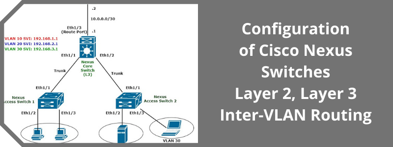
As shown in the network diagram below, the topology includes two Nexus access switches (AccessSwitch 1 and AccessSwitch 2) and one Nexus Core Layer 3 switch for performing routing and communication between Layer 2 VLANs (i.e inter-VLAN routing).
Moreover, the Core Nexus switch is also connected to a border router with a pure Layer 3 Interface (Route Port) as we will see in the configuration below.

Here are the VLAN and IP Subnet details of our network topology:
- VLAN 10 – HR Department – L3 Subnet 192.168.1.0/24
- VLAN 20 – Finance Department – L3 Subnet 192.168.2.0/24
- VLAN 30 – Guests – L3 Subnet 192.168.3.0/24
Note that if you only have the Layer 2 Access Switches in the network, hosts will be able to communicate only within the same VLAN but will not be able to talk to other hosts belonging to a different VLAN.
In order to establish inter-VLAN communication (i.e routing between hosts belonging to different VLANs) you need to have a Layer 3 routing engine in the network.
This L3 engine is provided by the Nexus Core Switch (which must have an appropriate Layer 3 image and license).
On the Core Switch, for each Layer 2 vlan we will configure an SVI (Switch Virtual Interface) which will serve as the default gateway for all hosts connected to that particular VLAN.
For example, hosts in VLAN 10 will have as default gateway the IP address 192.168.1.1.
Let’s now see the configuration below.
Configuration
Let’s see the configuration commands for each Nexus switch in our example scenario:
Configuration of Nexus Core L3 Switch
! First Create the Layer 2 VLANs
vlan 10
name HR
vlan 20
name Finance
vlan 30
name Guests
! Now Create the Layer 3 SVI interfaces
feature interface-vlan
interface vlan 10
ip address 192.168.1.1/24
no ip redirects
feature interface-vlan
interface vlan 20
ip address 192.168.2.1/24
no ip redirects
feature interface-vlan
interface vlan 30
ip address 192.168.3.1/24
no ip redirects
! Next configure the physical interfaces (trunk ports and routed port)
interface ethernet 1/1
description To AccessSwitch1
switchport
switchport mode trunk
no shutdown
interface ethernet 1/2
description to AccessSwitch2
switchport
switchport mode trunk
no shutdown
interface ethernet 1/3
description to Border Router
no switchport
ip address 10.0.0.1/30
no shutdown
! Configure static default route towards the border router and save the config
ip route 0.0.0.0 0.0.0.0 10.0.0.2
copy running-config startup-config
Configuration of Nexus L2 Access Switch 1
! First Create the Layer 2 VLANs
vlan 10
name HR
vlan 20
name Finance
vlan 30
name Guests
! Configure trunk port towards the Core Switch
interface ethernet 1/1
description To CoreSwitch
switchport mode trunk
no shutdown
! Assign access ports to VLAN 10
interface ethernet 1/2
switchport mode access
switchport access vlan 10
no shutdown
interface ethernet 1/3
switchport mode access
switchport access vlan 10
no shutdown
copy running-config startup-config
Configuration of Nexus L2 Access Switch 2
! First Create the Layer 2 VLANs
vlan 10
name HR
vlan 20
name Finance
vlan 30
name Guests
! Configure trunk port towards the Core Switch
interface ethernet 1/1
description To CoreSwitch
switchport mode trunk
no shutdown
! Assign access ports to VLAN 20 and VLAN 30
interface ethernet 1/2
switchport mode access
switchport access vlan 20
no shutdown
interface ethernet 1/3
switchport mode access
switchport access vlan 30
no shutdown
copy running-config startup-config
NOTE
On the border router you must configure static routes towards 10.0.0.1 (core switch IP) in order to reach the 3 subnets connected to the three VLANs in the network.
Related Posts
- What is Cisco Switch Virtual Interface (SVI) – Configuration Example and Explanation
- Deleting the VLAN Database from a Cisco Switch (IOS or Nexus)
- What is Cisco Virtual Port Channel (vPC) – Explained and Discussed
- Discussion and Explanation of BPDU Guard (With Cisco Config Example)
- From Reactive to Proactive: Mastering Network Performance with Switch Monitoring