Networks Training

  • About
  • My Books
  • SUGGESTED TRAINING
  • HOME
  • Cisco Networking
    • Cisco General
    • Cisco IOS
    • Cisco VPN
    • Cisco Wireless
  • Cisco ASA
    • Cisco ASA General
    • Cisco ASA Firewall Configuration
  • Certifications Training
    • CCNA Training
    • Cisco Certifications
    • I.T Training
  • General
    • General Networking
    • IP Telephony
    • Network Security
    • Product Reviews
    • Software
  • Cisco Routers
  • Cisco Switches
You are here: Home / Cisco Switches / Layer 2 VLAN Configuration on a Cisco Switch (with Example)

Layer 2 VLAN Configuration on a Cisco Switch (with Example)

Written By Harris Andrea

This post will deal with creating Layer 2 VLANs on Cisco switches and performing all relevant configurations.

Up to 4094 VLANs can be configured on Cisco catalyst switches. By default, only VLAN 1 is configured on the switch, so if you connect hosts on an out-of-the-box switch they all belong to the same Layer 2 broadcast domain.

The need to configure several Layer 2 VLANs on a switch arises from the need to segment an internal Local Area Network (LAN) into different IP subnetworks.

If you want for example to separate the different departments of your enterprise into different IP subnetworks, then each department should belong to its own Layer 2 VLAN. For example, let’s assume the following scenario:

  • Accounting Department: IP Subnet 192.168.2.0/24 –> VLAN 2
  • Management Department: IP Subnet 192.168.3.0/24 –> VLAN 3
  • Engineering Department: IP Subnet 192.168.4.0/24 –> VLAN 4

By separating the internal LAN into different IP subnets (and thus different VLANs) allows the network administrators to enforce traffic restrictions if needed between departments and have better control of internal hosts.

VLAN assignment on a switch is configured on a per-interface basis. That is, each switch port interface is assigned individually into a Layer 2 VLAN.

If you have more than one switch connected and you want the same VLANs to belong across all switches, then a Trunk Port must be configured between the switches.

The Trunk Port passes all VLANs between the switches. Let’s see the following network scenario to help us clarify some concepts.
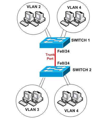
On the LAN network above, we have three VLANs. VLAN 2,3, and 4. VLAN 4 belongs both to SWITCH 1 and SWITCH 2, therefore we need a Trunk Port between the two switches in order for hosts in VLAN4 in Switch 1 to be able to communicate with hosts in VLAN4 in Switch 2.

MORE READING:  Private VLAN Configuration on Cisco Switches (Example Configuration)

The ports of the two switches shall be configured as following:

SWITCH 1:
Fe0/1 – Fe0/2 –> VLAN 2 (Accounting)
Fe0/10 – Fe0/11 –> VLAN 4 (Engineering)
Fe0/24 –> Trunk Port

SWITCH 2:
Fe0/1 – Fe0/2 –> VLAN 3 (Management)
Fe0/10 – Fe0/11 –> VLAN 4 (Engineering)
Fe0/24 –> Trunk Port

Table of Contents

  • How to Create and Configure VLANs on Cisco Switches
  • Verification
  • Communication Between VLANs
  • Related Posts

How to Create and Configure VLANs on Cisco Switches

Switch 1 Configuration:
!  Create VLANs 2 and 4 in the switch database
Switch1# configure terminal
Switch1(config)# vlan 2
Switch1(config-vlan)# name Accounting
Switch1(config-vlan)# end

Switch1(config)# vlan 4
Switch1(config-vlan)# name Engineering
Switch1(config-vlan)# end

!  Assign Ports Fe0/1 and Fe0/2 in VLAN 2
Switch1(config)# interface fastethernet0/1
Switch1(config-if)# switchport mode access
Switch1(config-if)# switchport access vlan 2
Switch1(config-if)# end
Switch1(config)# interface fastethernet0/2
Switch1(config-if)# switchport mode access
Switch1(config-if)# switchport access vlan 2
Switch1(config-if)# end

!  Assign Ports Fe0/10 and Fe0/11 in VLAN 4
Switch1(config)# interface fastethernet0/10
Switch1(config-if)# switchport mode access
Switch1(config-if)# switchport access vlan 4
Switch1(config-if)# end
Switch1(config)# interface fastethernet0/11
Switch1(config-if)# switchport mode access
Switch1(config-if)# switchport access vlan 4
Switch1(config-if)# end

!  Create Trunk Port Fe0/24
Switch1(config)# interface fastethernet0/24
Switch1(config-if)# switchport mode trunk
Switch1(config-if)# switchport trunk encapsulation dot1q
Switch1(config-if)# end

Switch 2 Configuration:
!  Create VLANs 3 and 4 in the switch database
Switch2# configure terminal
Switch2(config)# vlan 3
Switch2(config-vlan)# name Management
Switch2(config-vlan)# end

Switch2(config)# vlan 4
Switch2(config-vlan)# name Engineering
Switch2(config-vlan)# end

!  Assign Ports Fe0/1 and Fe0/2 in VLAN 3
Switch2(config)# interface fastethernet0/1
Switch2(config-if)# switchport mode access
Switch2(config-if)# switchport access vlan 3
Switch2(config-if)# end
Switch2(config)# interface fastethernet0/2
Switch2(config-if)# switchport mode access
Switch2(config-if)# switchport access vlan 3
Switch2(config-if)# end

MORE READING:  10 Different Types of Network Ethernet Switches for Small or Large Networks

!  Assign Ports Fe0/10 and Fe0/11 in VLAN 4
Switch2(config)# interface fastethernet0/10
Switch2(config-if)# switchport mode access
Switch2(config-if)# switchport access vlan 4
Switch2(config-if)# end
Switch2(config)# interface fastethernet0/11
Switch2(config-if)# switchport mode access
Switch2(config-if)# switchport access vlan 4
Switch2(config-if)# end

!  Create Trunk Port Fe0/24
Switch2(config)# interface fastethernet0/24
Switch2(config-if)# switchport mode trunk
Switch2(config-if)# switchport trunk encapsulation dot1q
Switch2(config-if)# end

Verification

If you want to verify that the physical interfaces are assigned properly to each VLAN, then run the following show commands:

SWITCH1#show vlan

VLAN Name                             Status    Ports
---- -------------------------------- --------- -------------------------------

1    default                          active    Fa0/3, Fa0/4
                                                Fa0/5, Fa0/6, Fa0/7, Fa0/8
                                                Fa0/9, Fa0/12
                                                Fa0/13, Fa0/14, Fa0/15

2   Accounting                        active    Fa0/1, Fa0/2
4   Engineering                       active    Fa0/10, Fa0/11


SWITCH2#show vlan

VLAN Name                             Status    Ports
---- -------------------------------- --------- -------------------------------

1 default                             active    Fa0/3, Fa0/4
                                                Fa0/5, Fa0/6, Fa0/7, Fa0/8
                                                Fa0/9, Fa0/12
                                                Fa0/13, Fa0/14, Fa0/15

3   Management                        active    Fa0/1, Fa0/2
4   Engineering                       active    Fa0/10, Fa0/11

Communication Between VLANs

Now, after separating the network into different VLANs, this means that we have created separate broadcast domains (one for each VLAN) and now hosts within the same VLAN can freely communicate between them (provided they belong also in the same Layer 3 subnet). 

On the other hand, hosts that belong in different Layer 2 VLANs can’t communicate between them. e.g hosts in VLAN 3 are not allowed to communicate with hosts in VLAN 4.

If you want to provide communication between hosts in different VLANs, then there must be a Layer 3 engine in the network (either a router or Layer 3 switch). In this article I have described how inter-vlan routing is configured on Layer 3 switches.

Related Posts

  • How to Configure a Loopback Interface on Cisco Router & Switch
  • Cisco Switch Layer2 Layer3 Design and Configuration
  • Description of Switchport Mode Access vs Trunk Modes on Cisco Switches
  • What is an SFP Port-Module in Network Switches and Devices
  • 8 Different Types of VLANs in TCP/IP Networks

Filed Under: Cisco Switches

Download Free Cisco Commands Cheat Sheets

Enter your Email below to Download our Free Cisco Commands Cheat Sheets for Routers, Switches and ASA Firewalls.

We use Elastic Email as our marketing automation service. By submitting this form, you agree that the information you provide will be transferred to Elastic Email for processing in accordance with their Terms of Use and Privacy Policy. Also, you allow me to send you informational and marketing emails from time-to-time.

About Harris Andrea

Harris Andrea is an Engineer with more than two decades of professional experience in the fields of TCP/IP Networks, Information Security and I.T. Over the years he has acquired several professional certifications such as CCNA, CCNP, CEH, ECSA etc.

He is a self-published author of two books ("Cisco ASA Firewall Fundamentals" and "Cisco VPN Configuration Guide") which are available at Amazon and on this website as well.

Comments

  1. andrew makonyola says

    April 15, 2009 at 4:24 am

    l would like to write online exams so l dont know where to pay the examination fee?am from malawi.

  2. BlogAdmin says

    April 15, 2009 at 9:47 am

    Hello,
    There should be a local Cisco certified examination center in your country where you can take the exam. Search Cisco about certified testing centers for your country.

  3. philip says

    April 22, 2009 at 12:17 am

    how to connect to switches using vlan i.e on one switch we have vlan4 and on the other I want also vlan 4 but one switch is having different ips so how to connect 2 switches

  4. BlogAdmin says

    April 22, 2009 at 1:31 am

    Hello Philip,

    Thanks for visiting. If you have Vlan4 on both switches, you configure them exactly as I show on the post above. You need to have a trunk port between the two switches. It does not matter if the IP addresses of the switches are different. The IP address is only for management purposes for a Layer 2 switch. The only thing you need to make sure is that your hosts in Vlan 4 must be in the same IP subnet range.

  5. Ravi says

    May 15, 2009 at 7:51 pm

    Thanks a lot for the article. It has almost helped me doing my project. But I am facing a problem.

    I wanna trunk two switches without using access mode, so that the switch would update its VLAN table dynamically.

    I have created trunk on Switch_A and gave its domain name. I did the same for the Switch_B. But when I am creating a VLAN on Switch_A, Switch_B doesn’t update its database. Can you help me?

    Thanks
    Ravi

  6. BlogAdmin says

    May 16, 2009 at 1:37 am

    Basically you are refering to VTP (Vlan Trunking Protocol). To configure VTP, you need to specify one switch as VTP SERVER and all other switches as VTP CLIENT. Then, you configure VLANs only on the VTP SERVER switch, and all these VLANs are propagated and appear also on the Client switches.

    Configure VTP SERVER:
    SWITCH-A(config)#vtp domain whatever
    SWITCH-A(config)#vtp mode server

    Configure VTP CLIENT:
    SWITCH-B(config)#vtp domain whatever
    SWITCH-B(config)#vtp mode client

    Thats is. You can configure also a password for the VTP domain which must be configured on ALL switches.

  7. ma says

    June 30, 2009 at 6:42 am

    really helpful! I like the way u put ur ideas. what should i do to assign 8 ports in one vlan at once. it is a little tiresome to do it one at a time.

  8. BlogAdmin says

    June 30, 2009 at 3:34 pm

    To configure multiple interfaces at one shot you can use the “interface range” command. See example below:

    Switch1(config)# interface range fastethernet0/1 – 8
    Switch1(config-if-range)# switchport mode access
    Switch1(config-if-range)# switchport access vlan 2

    The configuration above will put interfaces 1 to 8 into Vlan 2

    Cheers
    Harris

  9. Suraj says

    July 8, 2009 at 1:05 am

    Great! very happy to see such greate scenario and configuration, if I add Router-A with Switch one for IVR (Inter-vlan Routing) Kindly help in this regard.

  10. BlogAdmin says

    July 8, 2009 at 4:24 am

    If you want to create intervlan routing between all three VLANs 2,3,4 then you need to connect a router on one trunk port of ANY switch (either switch 1 or switch 2) and then configure DOT1Q subinterfaces on the router.

    Assume that we will use port 0/23 of SWITCH 1 to connect the router. This switch port must be TRUNK port:
    SWITCH1:
    ————
    interface FastEthernet0/23
    switchport trunk encapsulation dot1q
    switchport mode trunk

    ROUTER:
    ————-
    interface FastEthernet0
    no ip address

    interface FastEthernet0.2
    encapsulation dot1Q 2
    no shutdown
    ip address 192.168.2.1 255.255.255.0

    interface FastEthernet0.3
    encapsulation dot1Q 3
    no shutdown
    ip address 192.168.3.1 255.255.255.0

    interface FastEthernet0.4
    encapsulation dot1Q 4
    no shutdown
    ip address 192.168.4.1 255.255.255.0

    Now, all hosts in VLAN2 for example must have as default gateway the router address 192.168.2.1. Similarly with other hosts in the other VLANs must have as default gateway the corresponding router subinterface address.

  11. deeps says

    July 14, 2009 at 7:00 am

    if I add interface in first switch (server mode)to Example -fe 0/10 to vlan 100, the same interface fe0/10 gets added in second switch also, what if i need to add fe0/10 of second switch to different vlan–pls give ur suggestion

  12. BlogAdmin says

    July 14, 2009 at 11:49 am

    Hello deeps,

    If the first switch is a VTP server and you add fe0/10 to vlan 100, then the same interface fe0/10 in second switch will NOT be added to vlan 100 as you assume in your comment. What will happen is that vlan 100 will be created to the second switch on which you can add interfaces accordingly. The function of VTP is to create vlans on vtp server and have those vlans created automatically to the other switches. Then you add interfaces to vlans manually according to your network design.

  13. patice says

    October 17, 2009 at 5:27 pm

    Great idears, clear explanation. Thanks for your labs.

    Dear Sir, i have a problem with one of my switches dropping one a day and the internet gone within the whole building. To get the internet Back up i have to turn the Cisco switch, Catalyst 3550, off and back on. this causes serious disruption on my network.
    The network has about 600 users on 1 VLAN only, but the Catalyst 3550 has only one port F0/22 connected to the internet.
    Please I need help…

  14. BlogAdmin says

    October 18, 2009 at 3:27 pm

    I would suspect a broadcast storm situation. 600 users on the same Vlan are a lot. Sometimes, a broken ethernet card on one host might cause broadcasts which could bring the whole network down. I would suggest to divide your network to smaller vlans and subnets.

  15. Patice says

    October 19, 2009 at 1:36 am

    Thanks Sir,
    I would like to explain more. We have about 13 spread accross the building, they are from different vendors such as 3Com – HP – Cisco.

    They did not think about VLANs when they were build, maybe there were only few user. but as the compny grew up, no body thought about it as there were no cisco enginneer on site.

    So they all on VLAN 1. The problem we have is not the whole network that goes down, but the internet. every day it goes down at lest once.
    When it does we have to turn the Cisco catalyst 3550 off and on, wait for a little while- 3min – and the internet is back.

    This Cisco catalyst 3550 has one port connected to the internet F0/1, and F0/24 to a distribution switch for network users.

    I appreciate we have to divide into many smaller VLANs, but how can broadcast storm affects the 3550 switch as its main purpose is only the internet connestion with two ports only in use.

    Thank you for your time

  16. BlogAdmin says

    October 19, 2009 at 2:44 am

    I would suggest to manually fix the speed and duplex settings on the 3550 switch for both F0/1 and F0/24. You can do this under interface configuration mode using:
    switch(config-if)# speed 100
    switch(config-if)# duplex full

    Other than that I can not help you much. Unfortunately is very difficult to troubleshoot a Layer 2 network just from a blog post communication.

    Good luck

  17. Beginner says

    October 21, 2009 at 3:01 am

    Thanks it was very helpful.I have one scenario:
    Cisco 3550 has VLAN5 with 16 ports (FE0/33-0/48)with ip 192.168.x.x/24 ,because 3550 doesn’t do NAT, on one of the ports of that VLAN is connect simple router just for NAT, and that router is connect to cisco 3750 too, and with 3750 i’m on internet. How do a configure the 3550 to be able with my computer with Public IP 77.x.x.x and connected to 3750 be on the same VLAN5 and ip of the range 192.168.x.x/24.Thanks

  18. BlogAdmin says

    October 21, 2009 at 3:14 am

    Hello Beginner!!

    Sorry but I didn’t understand much from what you are saying. If I understand your question correctly, you will need to connect a router with two interfaces. The internal interface of the router should be on the 3550 switch and have IP address in the range 192.168.x.x, and the outside interface of the router should have the public IP address 77.x.x.x. Then, you can configure the router to perform NAT.

  19. Beginner says

    October 21, 2009 at 4:31 am

    Sorry. I have cisco 3550 and 3750.On cisco 3750 there is no VLAN created, every FE0/ port has Public IP and goes to internet. On 3550 i create VLAN5 with private IP and assign to that VLAN 16 FE ports.What is the best way to communicate:One host from VLAN5 from 3550 (IP address:192.168.3.x) and another host from 3750. Sorry and thanks anyway. (For communication between 3550 and 3750 i use simple router just for NAT)

  20. Bertino says

    October 30, 2009 at 10:22 am

    Hi Beginner, I am new as well.
    You don’t have to use a Router to allow host to communicate between the 3550 and 3750 catalyst switches.
    1/ You could, if you want, create the same VLANs on both switches and add FastEthernet ports to them. Please not that the ports, on the switches do not have to match but the VLANs do.
    2/ The ports linking the switches, on both sides, should be configures as TRUNK ports to tag the packets travelling accross.

    Another possibility would be to allow the PCs on different VLANs to talk. This could be done with your router (Routing on a stick), but you switches are LAYER 3 and can handle this job. All you shall have to do will be to issue the “ip routing” command in global configuration mode. then the VLANs ip addresses will be the default gateway of the clients PCs.

    The blogAdmin has a clear explanation on his web site, please have a look it is very good and easy.

    Thanks

  21. BlogAdmin says

    October 30, 2009 at 10:30 am

    Thanks Bertino for the clarification. You don’t sound a “Beginner” to me by the way :)

    You can visit my post about Layer 3 Switch Routing for more information about intervlan routing on the same switch.

    Thanks guys for reading my blog.

    Cheers

    Harris

  22. Beginner says

    November 10, 2009 at 4:49 am

    Thank you very much for the help.
    I have another question:Is there another way to communicate two PCs that are in two different L3 switches but on the same VLAN.In this scenario I don’t want to use trunks between L3 switches , and they are communicate between them with L3 interfaces (OSPF between this switches).Is this possible.Thx again.

  23. BlogAdmin says

    November 10, 2009 at 7:06 am

    Sure you can do this. On a Layer3 switch you can configure an interface to work as a routed port (just like a normal router interface). Use the command “no switchport” for that interface and then configure an IP address as you would for a regular router interface. Configure two routed ports on the switches (one for the first switch and one for the second) and then connect those two routed ports together (back-to-back with a cross over cable). The IP addresses of the two routed ports must be in the same subnet (e.g 192.168.1.1/24 on the first switch and 192.168.1.2/24 on the second switch). Then configure an SVI interface on both switches (e.g interface Vlan 1) and assign IP address (e.g 10.10.10.1/24 on first switch and 10.20.20.1/24 on second switch). The two PCs must be in the respective subnet (one of them in 10.10.10.0/24 subnet and the other one in 10.20.20.0/24 subnet).

    Is this confusing or you got the idea?

  24. Beginner says

    November 10, 2009 at 8:42 am

    It works, Thx a lot. BlogAdmin rules :)

  25. Patice says

    November 10, 2009 at 7:37 pm

    Thanks BlogAdmin

  26. Cristina says

    November 11, 2009 at 4:20 am

    Thx for the post. But what if I want the VLAN to mirror from one L3 switch to the other? For example, if i attach host on Vlan5, no matter if I attach it on the first L3 switch or on the second, that host to belong on the same VLAN.
    Is it possible the SVI interfaces on both switches (e.g interface Vlan 5) to have IP address from the same subnet(e.g 10.10.10.0/24)?

    Thx in advance.

  27. BlogAdmin says

    November 11, 2009 at 4:30 am

    Cristina,

    What you describe above can NOT be done. Once you configure your switches as Layer3 switches, it is like having routers connecting your network subnets, which means that the networks must have different IP subnets across the interfaces of the layer3 device. What you want can be achieved only if you have plain Layer2 switches and you don’t configure layer3 functionality (see my original post at the beginning of this page).

  28. Douglas says

    November 13, 2009 at 8:07 am

    HI Cristina, I am a beginner
    Your Scenario has to be done through TRUNKING for INTER VLAN communication. But as far as the Beginner’s question is consern, as the BlogAdmin says it cannot be done.

    First the Uplinks msut be L3, by typing the command “no switchport”. This means at this level the switch acts as a Router, and consequently the other VLAN on your second L3 must be on a different subnet.

    Please note that the Uplinks between the two L3 switches must be on the same subnet.

    please have a look at this site for a sample configuration http://www.ccna-ccnp-journey.co.nr

    credits to BlogAdmin

    Good luck!

  29. Patrice says

    November 26, 2009 at 1:19 am

    Dear blogAdmin, Thanks for the good work.
    I have a question that maybe out of this topic. I have to set up a VLAN for a small building, and i know how to design it.
    They have a PRINT Server and want every boby, from any vlan, to be able to print to any printer if they wish to.
    I am confused as i do not know ho to redirect traffic to the print server, or how it is going to work.
    Here is the design: 6 VLANs – a Server farm.

    My plan is to add all servers into one vlan, configure inter VLAN communication and then use Access-list, on the core switch, to deny what ever traffic i want to. I have no idear if it is a good way, or how the printing is going to work.

    Dear sir this job is voluntary, and i earn no money from it but i would like to get it done. It is my ever first network design, and i have no previous experience. The network has to go live on the 5th December, and i am nervous. Please i need your help.

    Thanks

  30. BlogAdmin says

    November 26, 2009 at 2:01 am

    Patrice,

    As I understand you already have a Layer3 switch (maybe the core switch?) in your network. Is that correct? If that is the case, then you will need to configure intervlan routing on your Layer3 switch. Check out my other post about configuring switch Layer3 routing for an example.

    As you already suggest, put all Server farm into one Vlan and segment also the rest users into other vlans, and use Access lists to control traffic flow. Regarding the PRINT server, you can put it into one of the “user” Vlans and since you will have intervlan routing configured on the Layer3 switch, all users from any Vlan will be able to find it by routing.

  31. Patrice says

    November 26, 2009 at 7:03 am

    Thanks BlogAdmin,
    Just been told we are not doing Acees-lists, but only inter VLAN routing as some staffs use to logon regardeless of the machine. I told them that the security part does not exist, without access list, but they said it will be done gradually.

    As you said, i have a 3Com layer 3 switch as core switch for the routing.
    I am going to put all servers in on VLAN, and the inter VLAN routing will take care of the access! is that right?
    About the Print server, i still do not understand why i should put it on the USER VLAN. The idear here is, not only 2 VLANs, but more than 4: ADMIN, HUMANRes, GUESTS, IT.

    If i understand well, if i put the print server into “ADMIN” VLAN for example, all users will be able to see it as inter VLAN will be configured.! Is that right?
    But what will happen if i put it with other servers, in the same VLAN?

    Dear Admin, i know i am taking your time, but this is my up-to-now life time networking project.

    Thanks for your promt response.

  32. BlogAdmin says

    November 26, 2009 at 8:01 am

    If you properly configure intervlan routing, and the hosts in each Vlan have the proper gateway address (which is going to be the IP you configured on the Layer3 switch), then all vlans will communicate with no problems. Regarding the Print server, I said ” any User” vlan meaning any appropriate vlan except the servers vlan. You can put it for example in the IT Vlan. The intervlan routing will take care of the rest.

  33. Patrice says

    November 26, 2009 at 8:16 am

    Thanks a lot,
    As an expert, how do you find my approach? Do you have any suggestions about what i said and how i am going to configure the network?

    Dear sir, anything you think could make it better is welcomed.
    This is my first experience, and i am always ready to learn.

    the other consrn is I found, on the switch that connects the building to the internet, that the port on our side turns amber and green, amber and green continously. but the internet works and stops a least 4 times every week.

    The internet switch is no managed by us, and so we have port F0/3 from that switch to another switch on our network.

    What i tought, without touching it is that there maybe a speed oer duplex mismatch between our switch port, and the internet switch port.
    What do you think as Expert?

    Thanks for your time…

  34. raoul says

    January 15, 2010 at 5:57 am

    Thanks a lot. but still got a question:
    we got 2 domain’s, each on their own vlan: students and personnel. from student vlan you cannot go to Personnel, the other way around is possible.
    I need to install new printers where both students and personnel can print on.
    How to do this without changing the setup above.
    a 3rd vlan with printers and printserver and own ip adresses?

  35. BlogAdmin says

    January 15, 2010 at 10:54 am

    Why don’t you install the printers in Student’s Vlans? With that, both students and personnel will be able to access the printers (since you said that personnel vlan can access the student vlan). You don’t have to create a new vlan just for the printers. This is my opinion.

    Regards

  36. Dila Ram Gurung says

    January 18, 2010 at 12:25 pm

    Is’nt there any software available using which i can learn to configure the switch or router. What about Packet tracer software

  37. BlogAdmin says

    January 18, 2010 at 1:27 pm

    Yes, you can use Packet Tracer (available only for Cisco Networking Academy students) to learn the basics of routing and switching. Packet Tracer is good up to CCNA level though. For more advanced topics (CCNP, CCIE level) is not enough.

  38. Tomislav says

    January 26, 2010 at 6:25 pm

    Hello everybody!
    I’m doing something i packet tracer. I have 3 switches and 1 is server and others are clients. When I create new VLAN on SERVER, that VLAN is automaticly created on other SWITCHES, but when I assign interfaces to that new VLAN, those interfaces won’t assign automaticly to that new VLAN on client switches. Can I do something to automaticly assign interfaces to VLAN from SERVER?

  39. BlogAdmin says

    January 27, 2010 at 3:51 am

    As I understand you are using Vlan Trunking Protocol (VTP) with a VTP server and VTP clients. The purpose of VTP is to create a vlan on the Server switch and have that vlan created automatically to all other switches. VTP however can NOT assign interfaces to those vlans. You must assign the interfaces manually.

  40. saihnaa says

    March 2, 2010 at 6:46 am

    Hi this is very need. Thanks

  41. BONEZ says

    March 3, 2010 at 5:00 am

    Hi Everybody i have a problem in my lab test may be some of you here know how to solve this problem..i have 2 layer 3 switch and in every switch it has 2 VLAN’s in every VLAN i assign an IP address the same IP to the other VLAN of other switch.

    SW1 @ VLAN1 = 10.10.10.0
    VLAN2 = 10.10.11.0

    SW2 @ VLAN1 = 10.10.10.0
    VLAN2 = 10.10.11.0

    VLAN1 in SW1 and VLAN2 in SW2 is ok but in VLAN1 in SW1
    and VLAN1 in SW2 cant communicate each other as well as in VLAN2 in SW1 and VLAN2 in SW2.

    i create a routing on it but it still not working.

    any idea is appreciated..

  42. BlogAdmin says

    March 3, 2010 at 8:22 am

    Hello,

    How are the two switches connected together? You need to configure a trunk port between the two switches

  43. BONEZ says

    March 4, 2010 at 1:16 am

    YES Sir i did it but it still can’t communicate the two VLAN in different switch and the same subnetwork but in different subnetwork in different switch is OK.

  44. BlogAdmin says

    March 4, 2010 at 10:18 am

    It means that you have a Layer3 boundary between the Vlans, that is why you can communicate with the vlan having a different subnetwork

  45. Hari Krishna says

    November 10, 2010 at 6:28 am

    Hi,
    My scenario as follows
    I have single gateway i wanted to have multiple vlans where every vlan has to exist from the single gateway.

    Ex: Gateway is 192.168.2.1
    VLan3 – 192.168.3.0
    VLan4 – 192.168.4.0

    i wanted to make 192.168.2.1 as gatway of all vlans

    Can you help me about this configuration
    Thanks

  46. Blog Admin says

    November 10, 2010 at 10:23 am

    Hari,

    You can not do this. Each Vlan and each Layer3 subnet must have a gateway which belongs to that subnet. When the computers in a particular vlan send an ARP request to find the MAC address of their default gateway, this ARP request will go only within their vlan. So if you assign them a default gateway which is on a different subnet and vlan, then it will not work.

  47. Hari Krishna says

    November 10, 2010 at 12:23 pm

    Hi,

    Thanks for update me since i am working in small environment i cannot setup multiple gateways for each vlan. is there any solution i can getrid from this situation using single gateway using the multiple vlans

    Thanks

  48. Blog Admin says

    November 10, 2010 at 2:45 pm

    Why you can not setup different gateway for the PCs in each vlan? Anyhow, I tested something today on a Layer3 switch which is not a “standard” configuration but it seems it works. Basically you create a loopback interface on the Layer3 switch and configure an IP address on the loopback (lets say 10.10.10.10/32). Then, assume vlan 2 is network subnet 10.2.2.0/24. On the PCs connected on Vlan 2 you can configure as default gateway the switch loopback address (10.10.10.10) and it seems that it works. If you have another vlan 3 with layer 3 subnet 10.3.3.0/24, then you configure again the loopback address (10.10.10.10) as default gateway for the hosts on that vlan. So you have a single IP address as default gateway for all hosts on your vlans.

    Again this is NOT a standard scenario

  49. chichoo says

    November 29, 2010 at 9:35 am

    Hi,
    My scenario as follows
    I have a 2811 router connected to a switch with multiple vlans where every vlan has to exit from the different gateway.

    Ex:
    VLan 1 – 10.2.0.2 Gateway is 10.2.0.1 works fine
    VLan4 – 10.30.0.2 Gateway is 10.30.0.1 which is not reachable

    Note: On the cisco router there are sub-interfaces of f0.1/1 10.2.0.1 255.255.255.0
    f0.1/2 10.30.0.1 255.255.255.0

    Can you help me out with what is wrong thanks

  50. Blog Admin says

    November 29, 2010 at 11:29 am

    First point: You must create the Layer2 vlans on the switch first. That is, vlan 4 must be created on the switch.

    Second point: The subinterface on cisco router must be assigned to a vlan using “encapsulation dot1q 4”

    Third point: The interface connecting the switch with the 2811 router must be trunk port.

  51. chichoo says

    November 30, 2010 at 8:52 am

    Thank you very much Admin..you are doing a great job for network administrators.

    Please i have a slight challenge i have been trying to figure out how two switches will work connecting to a fibre optic transmitter cable specifically two 3750 switches and the also the configuration to make them communicate.kindly assist .Thanks a million

  52. Imran says

    December 21, 2010 at 4:11 am

    How would one configure a switch without any VLAN?
    Why would be a reasonable response but please assume that there is no need to segment nor controll access.

    Thank you,

    Imran

  53. Blog Admin says

    December 21, 2010 at 3:22 pm

    Imran,

    A Cisco switch does not have any Vlan by default. If you get it out of the box, there is only the default Vlan (Vlan 1) which actually does not tag the traffic with any Vlan information, so its like you don’t have any vlan at all.

  54. zaheer says

    February 3, 2011 at 12:34 am

    we want to renew our company that have four departments and each department have 24 pc.my duty is to make a new wireless LAN and a vlan for each department and we receive two class c addresses from ISP.And we also start to run our own website for the products of company.

    can you suggest any scenario.
    regards

  55. Blog Admin says

    February 3, 2011 at 6:00 am

    I would do the following:

    Create a “Star” switch topology with a central Layer3 switch and “Star legs” connecting the 4 department switches. Then on each department switch create a Vlan for the specific department (where you will connect the 24 pcs) and also a Vlan for the WLan device. All department switches will connect to the central Layer 3 switch with a trunk port to carry all vlans. The Layer3 switch will have Layer3 vlan with IP address.

  56. dayorj says

    April 1, 2011 at 12:24 am

    Need some help here guys. I have a Catalyst 2960 L2 and 3960 L3 switches and as far as i know 3960 is a router switch. Is there a way the 3960 will run as a router for inter-vlan routing as we haven’t had a dedicated router yet. Or are there any other ways to configure the current switches for inter-vlan purposes?

  57. dayorj says

    April 1, 2011 at 1:44 am

    need some help guys. I have a catalyst 3960 L3 and 2960 L2 switches. Is it possible to make the 3960 function as an inter-vlan router as I haven’t had a stand alone router yet? if there are other ways for inter-vlan routing utilizing my two switches, please do let me know. Thanks.

  58. dayorj says

    April 1, 2011 at 1:46 am

    rather i have a 3560 switches… sorry for the typo.

  59. Blog Admin says

    April 1, 2011 at 9:00 am

    Yes you can use the 3560 Layer3 switch for intervlan routing. Lets say you have two vlans (vlan10 and vlan20) that you want to have routing between them. First you need to create the layer2 vlans on the 3560 and then create a layer3 SVI interface (“interface vlan 10” for example) on the switch and assign an IP address on that SVI. Also, create an SVI for vlan 20 and assign an IP address from the other subnet. These IP addresses on the SVI interfaces will act as the default gateway for your hosts that are connected on the corresponding vlans.

  60. dayorj says

    April 15, 2011 at 5:07 am

    Thanks for your idea Blog Admin. To be straight, i am just new to this stuff. However after relentless research and reading Cisco books i have come up to this configuration of mine. please do check my settings for verification.

    By the way, have tried enrolling 2 hosts under one vlan and unable to ping each other using the same configurations below.

    User Access Verification

    Password:
    Catalyst3560>ena
    Catalyst3560>enable
    Password:
    Catalyst3560#sh ru
    Building configuration…

    Current configuration : 5938 bytes
    !
    version 12.2
    no service pad
    service timestamps debug datetime msec
    service timestamps log datetime msec
    no service password-encryption
    service sequence-numbers
    !
    hostname Catalyst3560
    !
    boot-start-marker
    boot-end-marker
    !
    enable secret 5 $1$oBhY$Rb8SlhdSErAMpVxOFMD0h0
    enable password
    !
    !
    !
    macro global description cisco-global
    no aaa new-model
    system mtu routing 1500
    udld aggressive

    ip routing
    !
    !
    !
    mls qos map cos-dscp 0 8 16 24 32 46 46 56
    mls qos srr-queue input bandwidth 70 30
    mls qos srr-queue input threshold 1 80 90
    mls qos srr-queue input priority-queue 2 bandwidth 30
    mls qos srr-queue input cos-map queue 1 threshold 2 3
    mls qos srr-queue input cos-map queue 1 threshold 3 6 7
    mls qos srr-queue input cos-map queue 2 threshold 1 4
    mls qos srr-queue input dscp-map queue 1 threshold 2 24
    mls qos srr-queue input dscp-map queue 1 threshold 3 48 49 50 51 52 53 54 55
    mls qos srr-queue input dscp-map queue 1 threshold 3 56 57 58 59 60 61 62 63
    mls qos srr-queue input dscp-map queue 2 threshold 3 32 33 40 41 42 43 44 45
    mls qos srr-queue input dscp-map queue 2 threshold 3 46 47
    mls qos srr-queue output cos-map queue 1 threshold 3 4 5
    mls qos srr-queue output cos-map queue 2 threshold 1 2
    mls qos srr-queue output cos-map queue 2 threshold 2 3
    mls qos srr-queue output cos-map queue 2 threshold 3 6 7
    mls qos srr-queue output cos-map queue 3 threshold 3 0
    mls qos srr-queue output cos-map queue 4 threshold 3 1
    mls qos srr-queue output dscp-map queue 1 threshold 3 32 33 40 41 42 43 44 45
    mls qos srr-queue output dscp-map queue 1 threshold 3 46 47
    mls qos srr-queue output dscp-map queue 2 threshold 1 16 17 18 19 20 21 22 23
    mls qos srr-queue output dscp-map queue 2 threshold 1 26 27 28 29 30 31 34 35
    mls qos srr-queue output dscp-map queue 2 threshold 1 36 37 38 39
    mls qos srr-queue output dscp-map queue 2 threshold 2 24
    mls qos srr-queue output dscp-map queue 2 threshold 3 48 49 50 51 52 53 54 55
    mls qos srr-queue output dscp-map queue 2 threshold 3 56 57 58 59 60 61 62 63
    mls qos srr-queue output dscp-map queue 3 threshold 3 0 1 2 3 4 5 6 7
    mls qos srr-queue output dscp-map queue 4 threshold 1 8 9 11 13 15
    mls qos srr-queue output dscp-map queue 4 threshold 2 10 12 14
    mls qos queue-set output 1 threshold 1 100 100 50 200
    mls qos queue-set output 1 threshold 2 125 125 100 400
    mls qos queue-set output 1 threshold 3 100 100 100 400
    mls qos queue-set output 1 threshold 4 60 150 50 200
    mls qos queue-set output 1 buffers 15 25 40 20
    mls qos
    !
    crypto pki trustpoint TP-self-signed-1442936320
    enrollment selfsigned
    subject-name cn=IOS-Self-Signed-Certificate-1442936320
    revocation-check none
    rsakeypair TP-self-signed-1442936320
    !
    !
    crypto pki certificate chain TP-self-signed-1442936320
    certificate self-signed 01
    30820245 308201AE A0030201 02020101 300D0609 2A864886 F70D0101 04050030
    31312F30 2D060355 04031326 494F532D 53656C66 2D536967 6E65642D 43657274
    69666963 6174652D 31343432 39333633 3230301E 170D3933 30333031 30303031
    33375A17 0D323030 31303130 30303030 305A3031 312F302D 06035504 03132649
    4F532D53 656C662D 5369676E 65642D43 65727469 66696361 74652D31 34343239
    33363332 3030819F 300D0609 2A864886 F70D0101 01050003 818D0030 81890281
    8100C202 C024B854 2EBC7153 B7C57C0B 96DEBC6D DEF4AA59 80F08296 5E75C092
    D25F6A96 0E7B42E7 364E9461 C1133036 067F8E0A 9BABE393 86D9022D 035EC03A
    8A55241B 5CE78E1D 39DA7709 717F8D35 1696AACD 92388E5D 8F9F9009 DF0E6A84
    2B703250 C760AA17 E98FA820 638ABA9F 281326C0 78355325 E5159D32 7BE0397D
    8FB90203 010001A3 6D306B30 0F060355 1D130101 FF040530 030101FF 30180603
    551D1104 11300F82 0D436174 616C7973 74333536 302E301F 0603551D 23041830
    1680148C F7825564 79BEAD9D 69789215 E00DC4A3 A0C89E30 1D060355 1D0E0416
    04148CF7 82556479 BEAD9D69 789215E0 0DC4A3A0 C89E300D 06092A86 4886F70D
    01010405 00038181 00212CC4 466503C4 40BF9C6B 2EE75E17 37AECFD6 E45412C9
    6A2F3B6E E455C843 8DFAEEEB BDF5E2B8 694761E2 C65FB1C2 AD7CA3A6 72D5BEE8
    72086895 6E9BC8CA 302FEABC 4E089403 1DDC7E6F D45F7B74 BFE83B7D 321FA369
    975D0DCB 5A6DD224 88C5D2BA 44CA6D33 A316A9C0 9C6D249D CFE0EE9B F8BA0BE7
    354A2DA9 BAA1D598 55
    quit
    auto qos srnd4
    !
    !
    !
    errdisable recovery cause link-flap
    errdisable recovery interval 60
    !
    spanning-tree mode rapid-pvst
    spanning-tree loopguard default
    spanning-tree extend system-id
    spanning-tree backbonefast
    !
    vlan internal allocation policy ascending
    !
    !
    !
    !
    interface GigabitEthernet0/1
    description DAYORJ
    switchport mode access
    !
    interface GigabitEthernet0/2
    description REMAI
    switchport mode access
    switchport access vlan 2
    !
    interface GigabitEthernet0/3
    description REMAI
    switchport mode access
    switchport access vlan 3
    !
    interface GigabitEthernet0/4
    !
    interface GigabitEthernet0/5
    !
    interface GigabitEthernet0/6
    !
    interface GigabitEthernet0/7
    !
    interface GigabitEthernet0/8
    !
    interface GigabitEthernet0/9
    !
    interface GigabitEthernet0/10
    !
    interface GigabitEthernet0/11
    !
    interface GigabitEthernet0/12
    !
    interface GigabitEthernet0/13
    !
    interface GigabitEthernet0/14
    !
    interface GigabitEthernet0/15
    !
    interface GigabitEthernet0/16
    !
    interface GigabitEthernet0/17
    !
    interface GigabitEthernet0/18
    !
    interface GigabitEthernet0/19
    !
    interface GigabitEthernet0/20
    !
    interface GigabitEthernet0/21
    !
    interface GigabitEthernet0/22
    !
    interface GigabitEthernet0/23
    !
    interface GigabitEthernet0/24
    !
    interface GigabitEthernet0/25
    !
    interface GigabitEthernet0/26
    !
    interface GigabitEthernet0/27
    !
    interface GigabitEthernet0/28
    !
    interface Vlan1
    description DAYORJ-LAPTOP
    ip address 192.168.10.1 255.255.255.0
    !
    interface Vlan2
    description REMAI
    ip address 192.168.20.1 255.255.255.0
    !
    interface Vlan3
    description ROMMEL
    ip address 192.168.30.1 255.255.255.0
    !
    !
    ip default-gateway 192.168.0.222
    ip classless
    ip route 0.0.0.0 0.0.0.0 192.168.0.254
    ip http server
    ip http secure-server
    !
    !
    ip sla enable reaction-alerts
    !
    !
    !
    line con 0
    line vty 0 4
    password Virtual
    login
    line vty 5 15
    password Virtual
    login
    !
    end

    Catalyst3560#

  61. Blog Admin says

    April 15, 2011 at 5:12 am

    REMAI is Vlan 2 but your configured interface GigabitEthernet0/3 and assigned that to Vlan3. Change this to Vlan 2 and your hosts should communicate

  62. dayorj says

    April 16, 2011 at 8:01 am

    still the same. i can’t ping 2 host in the same vlan. please check my settings. what are other parameters missing? i know this is one simple basic configuration but i just couldn’t work it out.

    User Access Verification

    Password:
    Catalyst3560>en
    Password:
    Catalyst3560#sh ru
    Building configuration…

    Current configuration : 1824 bytes
    !
    version 12.2
    no service pad
    service timestamps debug datetime msec
    service timestamps log datetime msec
    no service password-encryption
    !
    hostname Catalyst3560
    !
    boot-start-marker
    boot-end-marker
    !
    enable secret 5 $1$0lng$xa8PJesyVEqkSEQJgcKtN0
    enable password $1$0lJesqkSEQJg
    !
    !
    !
    no aaa new-model
    system mtu routing 1500
    !
    !
    !
    !
    !
    !
    !
    !
    spanning-tree mode pvst
    spanning-tree extend system-id
    !
    vlan internal allocation policy ascending
    !
    !
    !
    !
    interface GigabitEthernet0/1
    !
    interface GigabitEthernet0/2
    description REMAI
    switchport access vlan 2
    switchport mode access
    !
    interface GigabitEthernet0/3
    description ROMMEL
    switchport access vlan 2
    switchport mode access
    !
    interface GigabitEthernet0/4
    !
    interface GigabitEthernet0/5
    !
    interface GigabitEthernet0/6
    !
    interface GigabitEthernet0/7
    !
    interface GigabitEthernet0/8
    !
    interface GigabitEthernet0/9
    !
    interface GigabitEthernet0/10
    !
    interface GigabitEthernet0/11
    !
    interface GigabitEthernet0/12
    !
    interface GigabitEthernet0/13
    !
    interface GigabitEthernet0/14
    !
    interface GigabitEthernet0/15
    !
    interface GigabitEthernet0/16
    !
    interface GigabitEthernet0/17
    !
    interface GigabitEthernet0/18
    !
    interface GigabitEthernet0/19
    !
    interface GigabitEthernet0/20
    !
    interface GigabitEthernet0/21
    !
    interface GigabitEthernet0/22
    !
    interface GigabitEthernet0/23
    !
    interface GigabitEthernet0/24
    !
    interface GigabitEthernet0/25
    !
    interface GigabitEthernet0/26
    !
    interface GigabitEthernet0/27
    !
    interface GigabitEthernet0/28
    !
    interface Vlan1
    ip address 192.168.10.1 255.255.255.0
    !
    interface Vlan2
    ip address 192.168.20.1 255.255.255.0
    !
    interface Vlan3
    ip address 192.168.30.1 255.255.255.0
    !
    ip classless
    ip http server
    ip http secure-server
    !
    !
    ip sla enable reaction-alerts
    !
    !
    !
    line con 0
    line vty 0 4
    password Telnet
    login
    line vty 5 15
    password Telnet
    login
    !
    end

    Catalyst3560#

  63. dayorj says

    April 16, 2011 at 8:08 am

    but i both hosts can ping their SVI (192.168.20.1)
    On each host default gateway is set to its SVI. is this the way it should be?

  64. Blog Admin says

    April 16, 2011 at 10:11 am

    I assume that you have connected both hosts on Gig0/2 and Gig0/3 of the switch and you have assigned IP in the range 192.168.20.x ? is that correct? So, the gateway of these two hosts must be the SVI of the switch (192.168.20.1) and they must be able to ping each other. Maybe you have a software firewall on the hosts? (maybe disable the windows firewall if they have one).

  65. dayorj says

    April 17, 2011 at 2:46 am

    Got it working. I just allowed the ICMP echo request to be exempted from the Windows firewall. Thanks very much Blog Admin! Now my second concern is how to route intervlan using the 3560. But i’ll have to leave this point to myself. A big thank you!

  66. dayorj says

    May 27, 2011 at 3:28 am

    Hi there! need again your help. I have two vlans created namely vlan 2 and 3. both can ping each other. however, they are unable to connect to the internet. please check my configurations below to see if there is a need to change or add something. thanks.

    User Access Verification

    Password:
    Alice3560>enable
    Password:
    Alice3560#sh ru
    Building configuration…

    Current configuration : 4296 bytes
    !
    version 12.2
    no service pad
    service timestamps debug datetime msec
    service timestamps log datetime msec
    no service password-encryption
    !
    hostname Alice3560
    !
    boot-start-marker
    boot-end-marker
    !
    enable secret 5 $1$AGZF$AC9xOFQKTz9QA57zmfsxo/
    enable password $AC9x$AGZF
    !
    !
    !
    no aaa new-model
    system mtu routing 1500
    ip routing
    !
    !
    !
    mls qos map cos-dscp 0 8 16 24 32 46 48 56
    mls qos srr-queue input bandwidth 70 30
    mls qos srr-queue input threshold 1 80 90
    mls qos srr-queue input priority-queue 2 bandwidth 30
    mls qos srr-queue input cos-map queue 1 threshold 2 3
    mls qos srr-queue input cos-map queue 1 threshold 3 6 7
    mls qos srr-queue input cos-map queue 2 threshold 1 4
    mls qos srr-queue input dscp-map queue 1 threshold 2 24
    mls qos srr-queue input dscp-map queue 1 threshold 3 48 49 50 51 52 53 54 55
    mls qos srr-queue input dscp-map queue 1 threshold 3 56 57 58 59 60 61 62 63
    mls qos srr-queue input dscp-map queue 2 threshold 3 32 33 40 41 42 43 44 45
    mls qos srr-queue input dscp-map queue 2 threshold 3 46 47
    mls qos srr-queue output cos-map queue 1 threshold 3 4 5
    mls qos srr-queue output cos-map queue 2 threshold 1 2
    mls qos srr-queue output cos-map queue 2 threshold 2 3
    mls qos srr-queue output cos-map queue 2 threshold 3 6 7
    mls qos srr-queue output cos-map queue 3 threshold 3 0
    mls qos srr-queue output cos-map queue 4 threshold 3 1
    mls qos srr-queue output dscp-map queue 1 threshold 3 32 33 40 41 42 43 44 45
    mls qos srr-queue output dscp-map queue 1 threshold 3 46 47
    mls qos srr-queue output dscp-map queue 2 threshold 1 16 17 18 19 20 21 22 23
    mls qos srr-queue output dscp-map queue 2 threshold 1 26 27 28 29 30 31 34 35
    mls qos srr-queue output dscp-map queue 2 threshold 1 36 37 38 39
    mls qos srr-queue output dscp-map queue 2 threshold 2 24
    mls qos srr-queue output dscp-map queue 2 threshold 3 48 49 50 51 52 53 54 55
    mls qos srr-queue output dscp-map queue 2 threshold 3 56 57 58 59 60 61 62 63
    mls qos srr-queue output dscp-map queue 3 threshold 3 0 1 2 3 4 5 6 7
    mls qos srr-queue output dscp-map queue 4 threshold 1 8 9 11 13 15
    mls qos srr-queue output dscp-map queue 4 threshold 2 10 12 14
    mls qos queue-set output 1 threshold 1 100 100 50 200
    mls qos queue-set output 1 threshold 2 125 125 100 400
    mls qos queue-set output 1 threshold 3 100 100 100 400
    mls qos queue-set output 1 threshold 4 60 150 50 200
    mls qos queue-set output 1 buffers 15 25 40 20
    mls qos
    !
    !
    auto qos srnd4
    !
    !
    !
    spanning-tree mode pvst
    spanning-tree extend system-id
    !
    vlan internal allocation policy ascending
    !
    !
    !
    !
    interface GigabitEthernet0/1
    !
    interface GigabitEthernet0/2
    description GEORGE
    switchport access vlan 2
    switchport mode access
    !
    interface GigabitEthernet0/3
    description JEROME
    switchport access vlan 3
    switchport mode access
    !
    interface GigabitEthernet0/4
    !
    interface GigabitEthernet0/5
    switchport trunk encapsulation dot1q
    switchport trunk native vlan 3
    switchport mode trunk
    srr-queue bandwidth share 1 30 35 5
    queue-set 2
    priority-queue out
    mls qos trust dscp
    auto qos trust
    macro description cisco-router
    spanning-tree portfast trunk
    spanning-tree bpduguard enable
    !
    interface GigabitEthernet0/6
    !
    interface GigabitEthernet0/7
    !
    interface GigabitEthernet0/8
    !
    interface GigabitEthernet0/9
    !
    interface GigabitEthernet0/10
    !
    interface GigabitEthernet0/11
    !
    interface GigabitEthernet0/12
    !
    interface GigabitEthernet0/13
    !
    interface GigabitEthernet0/14
    !
    interface GigabitEthernet0/15
    !
    interface GigabitEthernet0/16
    !
    interface GigabitEthernet0/17
    !
    interface GigabitEthernet0/18
    !
    interface GigabitEthernet0/19
    !
    interface GigabitEthernet0/20
    !
    interface GigabitEthernet0/21
    !
    interface GigabitEthernet0/22
    !
    interface GigabitEthernet0/23
    !
    interface GigabitEthernet0/24
    !
    interface GigabitEthernet0/25
    !
    interface GigabitEthernet0/26
    !
    interface GigabitEthernet0/27
    !
    interface GigabitEthernet0/28
    !
    interface Vlan1
    no ip address
    !
    interface Vlan2
    description REMOTE
    ip address 209.209.20.1 255.255.255.0
    !
    interface Vlan3
    description MIS
    ip address 209.209.30.1 255.255.255.0
    !
    ip default-gateway 192.168.0.254
    ip classless
    ip route 0.0.0.0 0.0.0.0 192.168.0.254
    ip http server
    ip http secure-server
    !
    !
    ip sla enable reaction-alerts
    !
    !
    !
    line con 0
    line vty 0 4
    password telnet
    login
    line vty 5 15
    password telnet
    login
    !
    end

    Alice3560#

  67. Blog Admin says

    May 30, 2011 at 11:28 am

    Most probably the problem is on routing. Make sure default gateway is correct and also that your default gateway has static routes pointing back to vlan2 and vlan3 subnets.

  68. Nikhil says

    August 31, 2011 at 12:03 pm

    thank you so much its very helpful,first time i am seeing a good nd simple way of teaching its very helpfull for beginers and experts also, the way u given the ansers for the question is great….
    once again i am giving full thanx for u its a great work…..

  69. Rehan says

    April 16, 2012 at 7:08 pm

    Nicely explained. Thanks heaps. Could you kindly show me how to assign an ip address to a switch. I have no vlans on my switch yet. so only default vlan (vlan1) is there. I want to telnet this switch through a laptop (in packet tracer) and for that I need to assign this switch an ip. Could you kindly assist. Regards

  70. Blog Admin says

    April 17, 2012 at 2:34 pm

    Rehan,

    You can configure IP address under Vlan1.

    Switch(config)# interface vlan 1
    Switch(config)# ip address 192.168.1.1 255.255.255.0
    Switch(config)# no shut

    Now since you don’t have any other vlans, when you connect a PC to any port of the switch you can telnet to it. Also, don’t forget to assign a password to the telnet lines (vty 0 4) and also configure an enable secret password as well.

Leave a Reply

Your email address will not be published. Required fields are marked *

This site uses Akismet to reduce spam. Learn how your comment data is processed.

Search this site

About Networks Training

We Provide Technical Tutorials and Configuration Examples about TCP/IP Networks with focus on Cisco Products and Technologies. This blog entails my own thoughts and ideas, which may not represent the thoughts of Cisco Systems Inc. This blog is NOT affiliated or endorsed by Cisco Systems Inc. All product names, logos and artwork are copyrights/trademarks of their respective owners.

Amazon Disclosure

As an Amazon Associate I earn from qualifying purchases.
Amazon and the Amazon logo are trademarks of Amazon.com, Inc. or its affiliates.

Search

BLOGROLL

Tech21Century
Firewall.cx

Copyright © 2023 | Privacy Policy | Terms and Conditions | Hire Me | Contact | Amazon Disclaimer | Delivery Policy

26 shares