In this blog I usually share practical configuration examples and how-to guides about Cisco networking devices and technologies (routers, switches, ASA firewalls etc).
However, there are a lot of people out there interested in more generic and fundamental networking topics because they either just starting out in this field or are learning the basic concepts for certification exams etc.
Therefore, I decided to start sharing also general basic networking articles which are not necessarily related to Cisco but they will certainly be useful to help you understand, design and implement network technologies.
Introduction
Although computer networks have been around for some decades, the evolution in this industry keeps growing every single day.
We cannot ignore the building blocks of networks, with communications models such as the OSI model, having 7 layers of operation.
For anyone who is not familiar with this model, all you need to know is that it serves as common language for network devices for communicating between them.
Starting from the top layer, which is the Application, down to the bottom layer, which is the physical layer, the OSI model is the basic pillar of networking.
The Data Link layer, which is also known as Layer 2, is where switching of frames takes place. At the Network layer, also known as Layer 3, is where packet routing is performed.
Routing and Switching serve as the core components of computer networks as we know them today. Although Layer 2 is not responsible for routing packets across networks, it is surely responsible for switching frames from one switch-port to another, before sending to the upper layers.
Collision Vs Broadcast Domains – Diagram
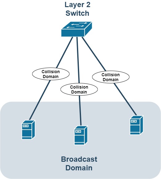
The diagram above shows a Layer 2 switch having one Broadcast Domain and three Collision Domains.
Basically, all hosts connected to the same switch (in the same Layer 2 VLAN) belong to the same broadcast domain. This means, all broadcast packets sent by one host will be received by all other hosts in the same broadcast domain (same VLAN).
On the other hand, each physical port link connecting a single host to the switch is considered a collision domain. If you have 3 hosts connected to the switch, there are 3 separate collision domains.
Let’s discuss these concepts in more details below:
What is a Collision Domain?
The term collision domain is basically used in LAN Switching, which occurs in Layer 2 of the OSI reference model.
Collision domains were prevalent at the beginning of the networking years where Hubs (instead of switches) were used to connect computers to the network
Because LAN communication in Hubs works on a shared medium, each device must wait and pay attention to the data being sent over the medium.
A collision domain refers to a network scenario whereby one device sends a frame out on a physical network segment, thus forcing every other device on the same segment to pay attention to the information sent out.
This scenario is not good in anyway – it is actually a problem when we look at it closely. The challenge comes in when two devices on the same network segment send data at the same time – a collision will occur, which forces the devices to resend the information.
Although Hubs are gradually becoming obsolete over time, some networks still make use of these network devices, which basically creates one big collision domain (regardless of the number of Hubs used).
Layer 2 switches are most commonly used in modern LAN networks, and this eliminates collisions. On an Ethernet Switch, a collision domain exists only on each physical switch-port, not on the whole switched network (as shown on the diagram above).
Because usually only a single host is connected to each switch port, there are no collisions in Ethernet Switches.
What is a Broadcast Domain?
Unlike collision domains, a broadcast domain is created when a group of computers are connected to the same network segment (same VLAN), making them listen to any broadcast message that is sent on the network segment.
You can also think of a broadcast domain as a logical separation on a network segment operating in Layer 2. As discussed on the diagram above, all hosts connected to the Layer 2 switch (in the same VLAN), belong to the same Broadcast Domain.
In terms of network devices, a router is used for creating multiple broadcast domains. This simply means that each router interface is considered as a border of each broadcast domain. Routers do not forward broadcasts, therefore a router interface is the boundary of the broadcast domain.
Routers can be quite expensive, which means you cannot rely on using many routers to create multiple broadcast domains. This brings about the concept of Virtual Local Area Networks – VLANs.
Even after switches breakup collision domains, by using each port as a collision domain, they still work as single broadcast domain, which needs to be broken using routers or VLANs.
A mechanism known as Carrier Sense Multiple Access/ Collision Detection (CSMA/CD) is used on LAN segments to detect and prevent collisions from happening.
Separate Broadcast Domains Using VLANs
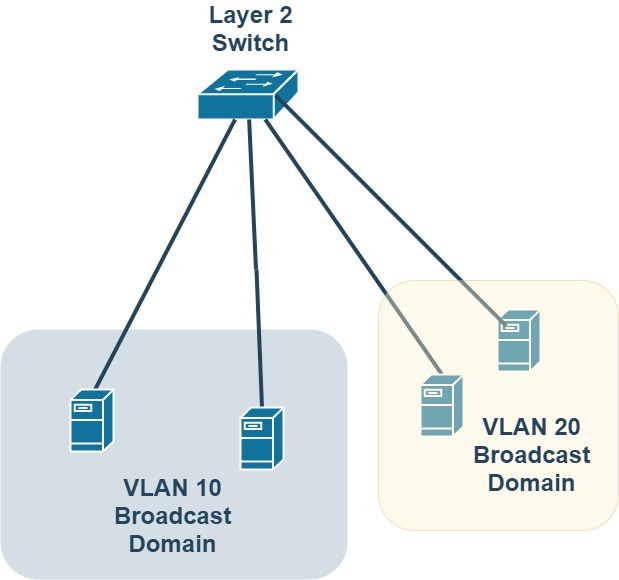
As we said above, there are two ways to separate broadcast domains. One is by using a router and another way is by using different VLANs on a Layer 2 switch.
As shown above, there are two VLANs (10 and 20) on the same switch. Each VLAN creates its own separate broadcast domain. Hosts in VLAN 10 can not communicate with hosts in VLAN 20 and vice-versa.
How do Routers Create a Broadcast Domain Boundary?
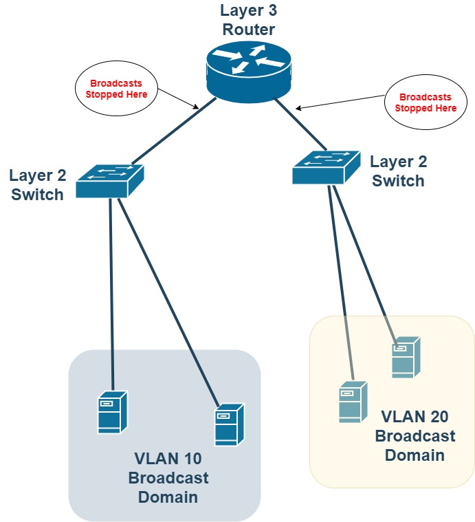
As mentioned before, Layer 3 Routers DO NOT forward broadcasts (this is my design). The diagram above shows how a router can act as a boundary for broadcast domains.
Although each Layer 2 switch in the example above is its own broadcast domain, by connecting the switch to a router there is a boundary between the two broadcast domains.
The scenario above however provides Layer 3 routing between the two VLANs so that hosts in VLAN 10 can communicate with hosts in VLAN 20 and vice-versa.
Related Posts
- Difference Between Routers and Switches in TCP/IP Networks
- 11 Different Types of IP Addresses Used in Computer Networks
- Compare and Contrast Network Topologies (Star, Mesh, Bus, Hybrid etc)
- 11 Networking Companies Like Cisco (Competitors)
- What is a Wildcard Mask – All About Wildcard Masks Used in Networking