Prepare to peek under the covers of how your data can travel from as little as a few inches to thousands of miles from device to device and through tens of network devices in the path.
In this article, we will explore the differences between a layer 3 Internet Protocol (IP) Packet and a layer 2 Frame.
We will begin with a brief discussion of the Open Systems Interconnection (OSI) model, after which, we will move onto the heart of the discussion, putting a layer 3 packet and layer 2 frame under the microscope.
OSI Discussion
Let’s begin with the OSI model. The OSI model serves to standardize the methodology in which computer network components communicate with one another.
There are 7 layers to the OSI model, data travels all the way from the tip of your ethernet cable (Layer 1) to the very web browser that you are reading this on (Layer 7).
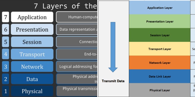
Figure 1 illustrates the architecture of the OSI model and provides a brief overview of what each layer does.
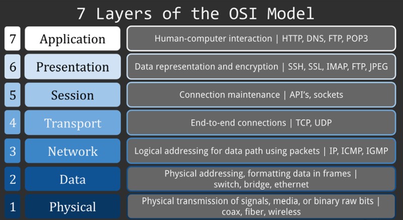
Figure 1 – OSI Model
As this article pertains to comparing layer 2 frame vs layer 3 packet, these will be explored in greater detail.
Data starts from the Application Layer (which is the interface to the user) and moves down the OSI layers.
As data moves down it is encapsulated inside data units. Each time data is “sent down” in the OSI model, this is referred to as “encapsulation”, and data “sent up” is called “de-capsulation”).
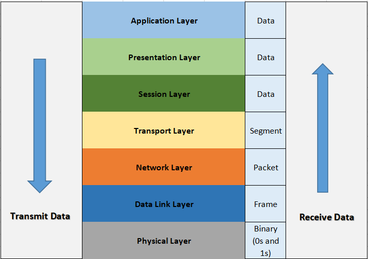
The picture above shows data travelling down from the Application Layer (Transmitted Data) and travelling up from the Physical Layer (Received Data).
Packet
Data at Network Layer 3 is called a “Packet”. This layer provides logical addressing and optimal path determination. So, the data that comes from your browser for example has a destination IP address. This is provided inside the IP packet header.
A layer 3 logical address is known as an “IP address” which enables the traffic to find its path.
A network device called a “router” works at Layer 3 and is used to forward traffic from its source to its destination, a process that relies entirely on IP addresses.
From the Layer 3 Network layer data is sent down to Data Link Layer 2.
Frame
Data at layer 2 is called a “Frame”, this layer (called Data Link layer) ensures the stability of data transmission between bordering devices.
This process builds upon raw binary bits that the physical layer uses. The data link layer carries out error detection and control using a Cyclic Redundancy Check (CRC) to prevent corrupted frames from progressing.
Layer 2 will receive the “packet” from above and encapsulate it inside a “frame”. This frame will have the hardware source and destination addresses (MAC address) and will then move down to the wire (physical layer).
In a typical computer network, Frames (Layer 2) are processed and forwarded by “Ethernet Switches“.
Now, let’s see the anatomy of Layer 2 frames and Layer 3 packets.
Layer 2 Ethernet Frame
The construction of an Ethernet frame is defined in the IEEE 802.3 standard. Figure below provides a visual representation of an Ethernet frame, followed by a description of each field in the frame.
![]()
Preamble – Notifies the receiver that a frame is being sent, which enables synchronisation. It allows the recipient to reserve bandwidth for the data stream before the actual frame is transmitted.
SFD (Start Frame Delimiter) – Signifies that the destination Media Access Control (MAC) Address field starts with the following byte. The SFD can also be condensed into the Preamble, hence it is characterised as 8 Bytes in many places.
Destination MAC – Determines who the recipient is. It contains the MAC address of the device for which data is intended.
Source MAC – Determines who the sender is. It contains the MAC address of the device that sourced the data.
Type – Determines the upper layer protocol within the Ethernet frame. You’re likely to stumble across the following hexadecimal values: 0x800 for IPv4, 0x86DD for IPv6 and 0x806 for ARP.
Data and Pad – Contains the payload data. Padding is added to satisfy the field’s minimum length requirement which is 46 bytes.
FCS (Frame Check Sequence) – Contains a 32-bit Cyclic Redundancy Check (CRC) which detects data corruption.
Layer 3 IP Packet
Moving up, we have the Layer 3 IP packet. Figure below is accompanied by an explanation of each field.
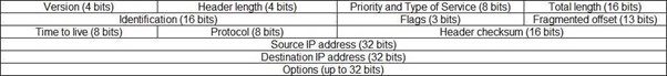
Version – The version of the IP protocol. IPv4 is denoted with a “4”.
Header length – The number of 32-bit words in the header (minimum value 5, maximum value 15).
Priority and Type of Service – Useful for quality of service as it determines how the data is treated.
Total length – Total packet length (header + data). (minimum value 20 bytes, maximum value 65,535 bytes).
Identification – Differentiates the group of fragments of a single IP datagram
Flags – Controls or identifies fragments.
Fragmented offset – Represents the number of Data Bytes ahead of the fragment in the particular Datagram.
Time to live (TTL) – It prevents the datagram from getting stuck in the network by limiting the number of Hops taken by a Packet before delivering to the Destination (1 hop means minus 1 TTL).
Protocol – Name of the protocol to which the data is to be handed to.
Header checksum – Used to check for corruption. If a packet arrives and the checksum is not what is expected, the packet will be discarded (it has errors).
Source IP address – The IP address of the sender.
Destination IP address – The IP address of the intended recipient.
Options – This allows for network testing and debugging, it is usually empty as it is not necessary.
You should know that Layer 3 IP packets are encapsulated inside Layer 2 Frames.
Comparison Table of Frame vs Packet
| Frame | Packet |
| Works at Layer 2 of OSI | Works at Layer 3 of OSI |
| Data Link Layer | Network Layer |
| Uses MAC addresses for addressing | Uses IP addresses for addressing |
| Used to detect corruption in data with CRC checks | Used for logical addressing and optimal path determination |
| Includes packets inside it | Packets are encapsulated inside frames |
| Usually have size of 1500 bytes | IP Packets can be much bigger and they get split inside the frames |
| Frames are forwarded by Ethernet Switches | Packets are forwarded by Routers |
Summary
A layer 2 frame and a layer 3 IP packet differ greatly. A frame is simple compared to an IP packet and focuses heavily on error checking (FCS and CRC).
The IP packet on the other hand is more complex than a frame and is geared toward travelling on much further and complex journeys through the network, as such, they utilise fields such as source and destination addresses, Time to Live, Type of Service, QoS (quality of service) etc.
Despite their differences, both layers work together to get data where it needs to go.
Related Posts
- Difference Between Routers and Switches in TCP/IP Networks
- 11 Different Types of IP Addresses Used in Computer Networks
- Compare and Contrast Network Topologies (Star, Mesh, Bus, Hybrid etc)
- 11 Networking Companies Like Cisco (Competitors)
- What is a Wildcard Mask – All About Wildcard Masks Used in Networking