Communication is key in modern life. Emails, phone calls, video calls are obvious examples. But, video streaming, ecommerce, eLearning, gaming etc are also a kind of communication. We are performing some type of communication in most of our life aspects.
Successful communication requires that all participating parties know how to “talk” to each other and, most important, do it using the same way (the same “language”), thus common rules have to be defined and followed.
Network and communication rules are called protocols. Protocols will ensure that all network components understand each other.
These protocols are implemented in software and hardware that are included in each host and networking device.
All the communication protocols used on a device will interact to provide reliable and quality communication with other parties.
A set of protocols are commonly called a stack. A stack illustrates the protocols as a layered hierarchy.
Each higher-layer protocol depends on the services of the protocols in the lower lever layer.
TCP/IP model and the OSI reference model are the two fundamental protocol stacks used by devices for communicating on a network, such as the Internet, a Local Area Network (LAN) etc.
In this article, we will explore the similarities and differences between TCP/IP and OSI models.
We will start with a brief presentation of each one. Then, we will highlight the various differences and similarities between them.
Comparison Table of the Main Features
Let’s first see a high-level table of the main features and characteristics of the two networking models.
| TCP/IP Model | OSI Model |
| Uses only 4 Layers | Uses 7 Layers |
| Older than OSI model (created first) | Newer than TCP/IP model |
| The Application Layer combines 3 Layers of OSI (Application, Presentation, Session) | Uses 3 different layers for user-centric functions (Application, Presentation, Session) |
| The Network Access layer combines 3 Layers of OSI (Data and Physical) | Uses 2 different layers for data transmission (Data and Physical) |
| Simpler but more difficult to troubleshoot | More granular and better troubleshooting |
| Not used much currently | Has the most adoption and usage in networks |
The OSI Model
OSI stands for “Open System Interconnection”. It’s a standard or reference written and maintained by ISO (International Standardization Organization), commonly called the OSI Model.
A reference model is mostly a theoretical description of all functions that must be completed to ensure a communication between two end points.
So, the primary goal of a reference model is to provide clear understanding of those functions and processes necessary for network communications.
The OSI model is used for data network design, operation specifications, and troubleshooting.
It uses the stack scheme (layers) to present different networking functions. As shown in Figure 1, the OSI model defines 7 layers:
- Application
- Presentation
- Session
- Transport
- Network
- Data link
- Physical layer.
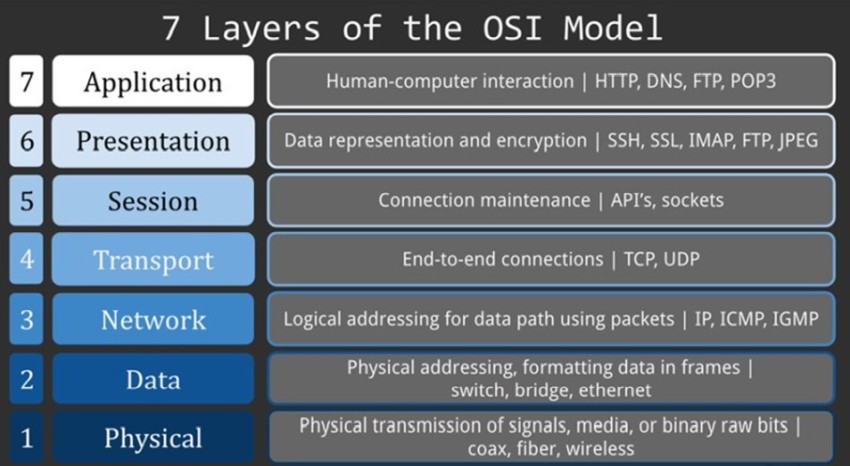
Figure 1: The OSI model
Starting from the top (Layer 7: Application) data will be created, processed and passed on to the next layer.
In the bottom layer (physical layer) data will be transformed (or coded) as transmission signal to be put on the physical wire.
This process refers to the emission phase of the communication.
The reception phase will be the opposite symmetric operation. It starts in the physical layer to decode the signal as binary data. Then it ends on the application layer.
In the following sections we will provide a brief description of each layer.
Application layer
The application layer contains the front-facing interface with the user.
Any user application which will send or receive data must invoke an “application layer” protocol.
For example, to access your favorite website you need to use a web browser on your laptop.
You don’t see it, but your browser uses the protocol HTTP or HTTPS to send requests and receive data from websites.
Different internet applications use different protocols: FTP for file transfer, POP3/SMTP for email exchange, SSH/Telnet or RDP for remote access etc.
All these are Application Layer protocols.
Presentation Layer
This layer will handle the format of the data exchanged between the protocols of the upper layer (the application layer).
It will synchronize what format to use and the needed configuration parameters by each side.
For example, when you are live streaming a video from your favorite streaming server, this layer will negotiate and set the suitable parameters for your device: data throughput, image quality, frame size, audio coding, etc.
Session Layer
The session layer provides dialog organization for the presentation layer. It means that this layer is responsible of time synchronization between the two devices on communication.
It will define dialog steps and different operations needed to be done in each part.
For example, when you launch a video call with your grandmother, the session layer will handle her number dialing, the ringing and the wait until she picks up and answers the call.
Transport Layer
Starting from the top, the transport layer will be the first layer to handle the TCP communication between the two end devices.
The upper layers were responsible for data formatting and synchronization.
This layer will ensure reliable packet transfers, data segmentation transfer and reassembly for each individual communication.
For example, if you are downloading a video, the transport layer will define the size of each fragment (called segment), their sequence and if they need a reception verification at the destination device.
Network Layer
Devices are grouped in networks, then networks are inter-connected and also grouped to form bigger networks called Autonomous Systems which in turn are connected to form the Internet.
This complex network setup needs a special protocol to find the best way or route from the sender device to the receiver.
The network layer will be responsible for this function. It will guarantee for the transport layer that each segment will be routed through intermediate equipment called routers in order to reach the final destination.
Data Link Layer
This layer forms the basic level of a network. It provides procedures for exchanging data frames between devices over a common media (usually over an Ethernet network found in LANs).
So, it will ensure communication between devices in the same Layer 2 network. For example, when you try to print a file with your office printer, the data link layer will ensure that all frames are received by the printer. A frame will be the unit used to split data in the Data Link layer.
Physical Layer
The physical layer protocols describe the needed functions to handle data transmission to and from a network device.
Those functions are related to the NIC (Network Interface Card) hardware and the media used. Wireless and wired communications will need obviously different functions.
The TCP/IP Model
In the 1970s decade, the first layered model for networking was created and consisted of two distinct protocols, namely the Transmission Control Protocol and the Internet Protocol.
The first part (TCP) provides a reliable connection-oriented service, while the other part (IP) provides a connectionless protocol.
The TCP/IP model defines the four basic functions that need to be ensured for any communication to be successful.
The TCP/IP protocol stack follows the structure of this model. As shows in Figure 2 below, this model defines four layers:
- Application
- Transport
- Internet
- Network Access
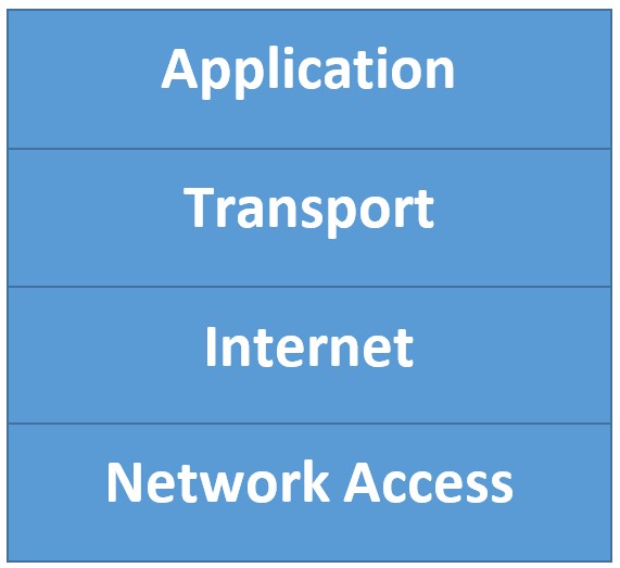
Figure 2: The TCP/IP Model
Application Layer
This layer will handle all operations related to the application. This means data creation, formatting and dialog synchronization are ensured.
In other terms, The TCP/IP Application layer is equivalent to the 3 Top layers defined by the OSI Model (Application+ Presentation+ Session).
Transport layer
This support communication between 2 end-devices across diverse networks.
Applications can choose different services to enhance specific delivery feature: minimum delay, minimum error or high speed and bandwidth.
Internet layer
It is responsible for routing data fragments (called packets) from the first sender device until reaching the receiver.
Packets of the same communication channel can use different paths. They will be reassembled before being delivered to the end device.
Network access layer
It controls the hardware devices and the media that make the network. It provides the electrical, mechanical and procedural functions to maintain data and signal transmission between any devices in the network.
Comparison: TCP/IP vs OSI Model
In this article we have described the two basic models used in tnetworking: OSI model and TCP/IP Model.
You can see clearly that those models have many features in common and provide almost the same role. But looking at them carefully they also have some differences.
In this part we will walk through a comparison between them and highlight their differences and similarities.
Differences Between TCP/IP vs OSI Models
- The TCP/IP model is older than OSI model (it was created much earlier).
- The 2 models differ in how they split the various networking functions. The OSI Model provides 7 layers while the TCP/IP uses only 4 layers to define its stack. Figure 3 below shows clearly the difference between the 2 stacks:
- The TCP/IP Application Layer includes various functions that provide data related services to end users. Those services are provided by the 3 upper layers in the OSI Model (Application+Presentation+Session).
- The network access layer in the TCP/IP model handles medium access and hardware control. While the OSI model splits this function into 2 layers. The Data Link and the Physical.
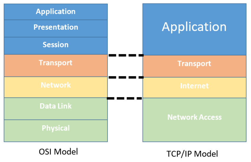
Figure 3 Mapping between OSI and TCP/IP models
- Although the TCP/IP model seems simpler than OSI (fewer layers), this means also that it is more difficult to troubleshoot in case of problems.
- The OSI model is the preferred and most frequently used model when designing, implementing and managing computer networks.
Similarities Between TCP/IP vs OSI Models
Figure 3 above shows also the similarities between the 2 models. The key similarities are in the transport and network layers.
- OSI layer 3 maps directly to the Internet layer of the TCP/IP model. In both models this layer describes protocols that address and route data packets through diverse networks.
- OSI layer 4 maps directly to the TCP/IP transport layer. In both models this layer provides a general description of services needed to assemble and reliably deliver data between two end-devices.
- Both protocol models provide logical ways of networking and for communication between two end-devices over modern networks (such as the Internet etc).
Summary
The TCP/IP and OSI Models help us visualize how the various protocols work together to enable network communications.
They depict the operation of the protocols occurring within each layer, as well as the interaction with the layers above and below each other.
The TCP/IP model focuses more on the protocols in use in its suite, while the OSI Model is a reference model. It describes the functions that must be completed at a particular layer, but does not specify exactly how a function should be accomplished.
Related Posts
- Difference Between Routers and Switches in TCP/IP Networks
- 11 Different Types of IP Addresses Used in Computer Networks
- Compare and Contrast Network Topologies (Star, Mesh, Bus, Hybrid etc)
- 11 Networking Companies Like Cisco (Competitors)
- What is a Wildcard Mask – All About Wildcard Masks Used in Networking