There are some networking terms and concepts that are so fundamental and important that every TCP/IP networking professional must know them by heart. One of these fundamental concepts is VLAN Trunking.
What is VLAN Trunking in Networking?
A VLAN Trunk falls into Layer 2 of the OSI model and is related to network switching.
When we speak about a “trunk” link in communication systems we usually refer to a “pipe” medium which carries multiple signals.
In Networking, a VLAN Trunk is a physical connection (usually between Ethernet switches) which is capable to carry traffic from multiple Layer 2 VLANs between the switches.
That is, if you have several VLANs on one switch and want the same VLANs to be configured on a different switch, then you must connect the two switches with a VLAN Trunk port (we will see an example below).
Although a Trunk port is usually a link between switches, you can also configure trunking between a switch and a router or a switch and a firewall device etc.
So, to summarize, consider a VLAN trunk as a link which carries traffic from multiple VLANs in a network switching environment.
Trunk Encapsulation Types
In order for a trunk port to pass multiple VLANs inside the link, the device must encapsulate the VLAN traffic using an encapsulation protocol.
The most common encapsulation protocol is IEEE 802.1Q (or simply called “dot1q”) which is a standardized protocol by the IEEE and is supported on all network devices that implement VLAN trunking.
Cisco devices support another proprietary trunking protocol called ISL (Inter-Switch Link) which is not widely used though. We recommend using the standardized 802.1Q encapsulation which is widely supported.
We will see how to configure this trunk encapsulation later on.
How to Configure VLAN Trunking on a Cisco Switch
We will use the following simple scenario to show an example configuration of VLAN trunks:
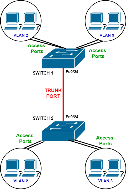
The diagram above illustrates a very simple but popular scenario whereby a Trunk Port link between two switches is configured in order to pass VLAN traffic between the two devices.
In the diagram above, we have SWITCH 1 which is configured with two Layer 2 VLANs (VLAN 2 and VLAN 3). These two VLANs are assigned to “access ports” on the switch which connect to user workstation computers.
Moreover, SWITCH 2 contains the same two VLANs as shown above. Therefore, computers connected to VLAN 2 on the first switch must be able to communicate with computers on VLAN 2 at the second switch. The same applies to VLAN 3.
In order to pass VLAN traffic (from the user hosts) between the two switches, a physical VLAN Trunk port must be configured as shown above.
Assuming that we will use port Fe0/24 on both switches, here is how to configure the trunk:
SWITCH 1
! Create Trunk Port on physical port Fe0/24
Switch1(config)# interface fastethernet0/24 <– configure Fe0/24 port
Switch1(config-if)# switchport mode trunk <– set the port as “trunk”
Switch1(config-if)# switchport trunk encapsulation dot1q <– set the encapsulation type to 802.1Q
Switch1(config-if)# end
SWITCH 2
! Create Trunk Port on physical port Fe0/24
Switch2(config)# interface fastethernet0/24 <– configure Fe0/24 port
Switch2(config-if)# switchport mode trunk <– set the port as “trunk”
Switch2(config-if)# switchport trunk encapsulation dot1q <– set the encapsulation type to 802.1Q
Switch2(config-if)# end
As shown above, first we set the port as “trunk” and then configure the encapsulation protocol (dot1q).
On some Cisco switch models, the only supported encapsulation is dot1q so you might not have to configure this command.
How to allow/restrict VLANs inside a trunk
Once you configure a Trunk port (as shown above), by default ALL VLANs (numbered 1 to 1005) between the two switches can pass through the trunk link.
That is, if you create additional VLANs on both switches, these new VLANs will be able to pass traffic between the two devices without any extra configuration on the trunk link.
Now, there are cases whereby you need to restrict which VLANs can pass traffic between the switches. Let’s see how to restrict VLANs on trunk links:
Using our example scenario above, assume that only VLANs 2 and 3 will ever be allowed through the trunk link and all other future VLANs must be restricted.
SWITCH 1
! Allow only VLANs 2 and 3 in the trunk ink
Switch1(config)# interface fastethernet0/24 <– configure Fe0/24 port
Switch1(config-if)# switchport mode trunk <– set the port as “trunk”
Switch1(config-if)# switchport trunk encapsulation dot1q <– set the encapsulation type to 802.1Q
Switch1(config-if)# switchport trunk allowed vlan 2-3 <– Allow only vlans 2 to 3
Switch1(config-if)# end
SWITCH 2
! Allow only VLANs 2 and 3 in the trunk ink
Switch2(config)# interface fastethernet0/24 <– configure Fe0/24 port
Switch2(config-if)# switchport mode trunk <– set the port as “trunk”
Switch2(config-if)# switchport trunk encapsulation dot1q <– set the encapsulation type to 802.1Q
Switch2(config-if)# switchport trunk allowed vlan 2-3 <– Allow only vlans 2 to 3
Switch2(config-if)# end
Now, if in the future you want to add an additional vlan in the trunk (let’s say vlan 4), you can add this as following:
switchport trunk allowed vlan add 4
Similarly, if you want to remove one of the vlans from the trunk (let’s say vlan 2), you can do so as following:
switchport trunk allowed vlan remove 2
What is the difference between a trunk port and access port?
On Layer 2 switches, each port can be configured as either Access Port or Trunk Port.
Access Ports are for connecting hosts or end-user devices (e.g computers, servers, other network hosts, routers, WiFi access points etc). These ports are assigned into a Layer 2 VLAN. If you don’t specify a VLAN number on an access port, by default it is assigned to the native default VLAN 1.
On the other hand, a Trunk Port is a point-to-point link for connecting two switches in order to pass traffic from multiple VLANs (as we described above). You never connect a host or computer to a trunk port.
VLAN Trunking Protocol (VTP)
In the previous section I explained how to configure VLAN trunking. That was a simple scenario with just two switches connected with a trunk port and having shared VLANs belonging to both switches.
Now, imagine the situation where you need to manage a huge Layer 2 switched network with tens or hundreds of switches and with VLANs spread across all switches in the network.
This would be a daunting task for any network administrator as he/she would have to connect on all switches and add or remove VLANs accordingly every time a new vlan is required in the network.
The Cisco Vlan Trunking Protocol (VTP) is a proprietary protocol available on all Cisco Catalyst switches and is designed to reduce the administration complexity and effort of managing many Layer 2 switches.
Basically you select one switch in the network (usually a central switch) and configure it to be the VTP Server of the network.
All other switches are configured as VTP Clients. Now, all VLAN administration is done on the VTP Server switch only.
If you add a new VLAN on the VTP server switch, this configuration change is propagated to all VTP client switches which automatically add this VLAN to their database.
Similarly, by deleting a VLAN on the server, all client switches delete that VLAN from their database.
A Cisco switch can be configured to operate in three VTP modes:
- VTP Server Mode – This is the default mode for switches. A VTP server switch can add, modify and delete VLANs for the whole VTP domain.
- VTP Transparent Mode – In this mode, the switch does not participate in the VTP domain. The switch passes VTP messages transparently to other switches but it does not synchronize its VLAN database according to these VTP messages.
- VTP Client Mode – This is the mode that you configure all switches that you need to have them synchronize their VLAN database according to the VTP server database.
Caution: Because VTP Server is the default mode, whenever you connect a new switch to the network, you need to make sure that you configure this switch as VTP Client BEFORE connecting it to the network.
This is to avoid the situation where a new switch connected might take the role of the VTP Server for the whole domain and since its VLAN database is still empty, it will cause all other switches in the network to delete all their VLANs.
Another important precaution is to configure also a password for the VTP domain, so that any new switch connected must have the domain password configured by the administrator before participating in the domain.
Cisco VTP Configuration:
VTP Server Switch:
! Configure first a name for the VTP domain
Vtp-server(config)# vtp domain mynetworkvtpname
! Configure the switch in server mode
Vtp-server(config)# vtp mode server
! Configure a password for the domain
Vtp-server(config)# vtp password vtp123
VTP Client Switch:
! Configure first a name for the VTP domain
Vtp-client(config)# vtp domain mynetworkvtpname
! Configure the switch in client mode
Vtp-client (config)# vtp mode client
! Configure the domain password in order to be able to participate
Vtp-client(config)# vtp password vtp123
Now every time you want to add or remove a Layer 2 vlan from the network, just create or delete the Vlan on the VTP Server switch and the change will be propagated to all other switches in the network.
Related Posts
- What is Cisco Switch Virtual Interface (SVI) – Configuration Example and Explanation
- Deleting the VLAN Database from a Cisco Switch (IOS or Nexus)
- What is Cisco Virtual Port Channel (vPC) – Explained and Discussed
- Discussion and Explanation of BPDU Guard (With Cisco Config Example)
- From Reactive to Proactive: Mastering Network Performance with Switch Monitoring