In today’s network infrastructures, you will encounter multivendor devices that need to communicate and interoperate. One requirement that you will find frequently in your work environment is to establish a secure VPN connection over the public internet between two different vendor devices.
As a network engineer you need to know that the best VPN technology to use for multivendor communication is IPSEC VPN. IPSEC is a standardized suit of protocols that is supported by all security vendors, therefore it offers the best option for interoperability.
Some VPN topics have already been discussed on this blog (such as vpn between ASA and pfsense , vpn between two Cisco ASA, VPN between routers with dynamic crypto maps, and other VPN scenarios).
In this post we will cover the configuration of an IPSEC VPN Tunnel between Cisco and Juniper routers in order to create a site-to-site VPN network over the Internet.
Devices used in this Lab: Cisco 891-k9 and Juniper SRX100H.
Software Versions: Cisco c890-universalk9-mz.151-4.M4.bin and Juniper 11.4R7.5
For easy understanding we will use a simple topology that covers Policy-Based IPSEC VPN between the two devices as shown on the diagram below.
NOTE: Policy-Based VPN is when a subset of traffic is selected (through a policy) for passing through the encrypted VPN tunnel. In our example below, only traffic between the two LAN subnets (192.168.10.0/24 and 192.168.20.0/24) will pass through the tunnel. All other traffic not matching the policy will flow to the internet unencrypted.
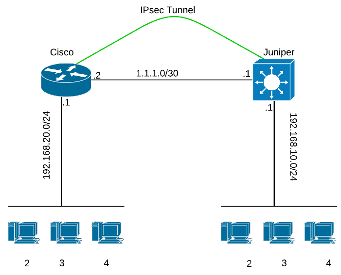
The idea is simple: configure a secure tunnel so that LAN 192.168.20.0/24 behind the Cisco router communicates with LAN 192.168.10.0/24 behind the Juniper router securely.
Remember that in any IPSEC configuration it is necessary that all the attributes for phase 1 & 2 need to be the same on both routers.
Lets begin with the Cisco 891 configuration:
Cisco 891 IPSEC VPN Configuration
Step 1:Configure ISAKAMP policy that contains the attributes used when phase 1 is negotiated
crypto isakmp policy 10
encr aes 256
hash md5
authentication pre-share
group 2
lifetime 28800
Step 2 : Create a pre-shared key used for authentication. We will use a static IP entry for more security, the password must be the same on both routers.
crypto keyring Cisco_Juniper
pre-shared-key address 1.1.1.1 key ciscojuniper
Step 3 : Configure ISAKAMP profile, in this case configure a specific peer.
crypto isakmp profile Cisco_to_Juniper
keyring Cisco_Juniper
match identity address 1.1.1.1 255.255.255.255
Step 4 : We are on our way for the phase 2 of the IPSEC tunnel, we will create the transform-set which tells the routers what encryption, hashing and encryption protocol to use when creating the IPSEC security associations.
crypto ipsec transform-set IPSEC_Cisco_Juniper esp-3des esp-md5-hmac
Step 5:Create the crypto map
crypto map IPSEC_Protection 10 ipsec-isakmp
set peer 1.1.1.1
set transform-set IPSEC_Cisco_Juniper
set isakmp-profile Cisco_to_Juniper
match address CiscoToJuniper
Step 6 : Create the ACL used to match the IP’s that are going to pass through the encrypted VPN tunnel
ip access-list extended CiscoToJuniper
permit ip 192.168.20.0 0.0.0.255 192.168.10.0 0.0.0.255
Step 7 : Apply the crypto map on the wan interface
interface GigabitEthernet0
description To Juniper
ip address 1.1.1.2 255.255.255.252
ip nat outside
crypto map IPSEC_Protection
Step 8: Create NAT exemption so that traffic between the two LAN subnets will be excluded from NAT operation. IPSEC does not work over NAT.
ip access-list extended NAT
remark IPSEC_Traffic_No_NAT
deny ip 192.168.20.0 0.0.0.255 192.168.10.0 0.0.0.255
remark Internet Traffic
permit ip 192.168.20.0 0.0.0.255 any
NOTE: We assume that the router is doing PAT (NAT overload) in order to provide access of the LAN subnet towards Internet. The full commands for implementing the NAT are not shown here.
Juniper SRX100 IPSEC VPN Configuration
The Juniper router, being a stateless firewall, requires a little more work and understanding of firewall zones to configure the IPSEC tunnel. I will try to keep the same order of steps as previously for easier understanding:
Step 1
set security ike proposal RP_IkeProposal authentication-method pre-shared-keys
set security ike proposal RP_IkeProposal dh-group group2
set security ike proposal RP_IkeProposal authentication-algorithm md5
set security ike proposal RP_IkeProposal encryption-algorithm aes-256-cbc
set security ike proposal RP_IkeProposal lifetime-seconds 28800
Step 2
set security ike policy RP_IkePolicy mode main
set security ike policy RP_IkePolicy proposals RP_IkeProposal
set security ike policy RP_IkePolicy pre-shared-key ascii-text ciscojuniper
Step 3&7
set security ike gateway RP_IkeGateway ike-policy RP_IkePolicy
set security ike gateway RP_IkeGateway address 1.1.1.2
set security ike gateway RP_IkeGateway external-interface fe-0/0/0
Step 4&5
set security ipsec proposal RP_IPSecProposal protocol esp
set security ipsec proposal RP_IPSecProposal authentication-algorithm hmac-md5-96
set security ipsec proposal RP_IPSecProposal encryption-algorithm 3des-cbc
set security ipsec proposal RP_IPSecProposal lifetime-seconds 3600
set security ipsec policy RP_IPSecPolicy proposals RP_IPSecProposal
set security ipsec vpn RP_IPSecVpn ike gateway RP_IkeGateway
set security ipsec vpn RP_IPSecVpn ike ipsec-policy RP_IPSecPolicy
Step 6 : Juniper is a stateless firewall and operates with security zones and not with normal ACL like Cisco does. Note: VLAN10 is the internal trusted zone. Interface fe-0/0/0.0 is the WAN untrusted interface.
set security zones security-zone trust address-book address Local_Network 192.168.10.0/24
set security zones security-zone trust host-inbound-traffic system-services all
set security zones security-zone trust host-inbound-traffic system-services ike
set security zones security-zone trust host-inbound-traffic protocols all
set security zones security-zone trust interfaces vlan.10
set security zones security-zone untrust address-book address Cisco_Network 192.168.20.0/24
set security zones security-zone untrust host-inbound-traffic system-services ike
set security zones security-zone untrust interfaces fe-0/0/0.0 host-inbound-traffic system-services all
set security zones security-zone untrust interfaces fe-0/0/0.0 host-inbound-traffic protocols all
Step 8 – some more zones configuration, this time for the security policy
set security policies from-zone trust to-zone untrust policy RP_TrustToUntrustPolicy match source-address Local_Network
set security policies from-zone trust to-zone untrust policy RP_TrustToUntrustPolicy match destination-address Cisco_Network
set security policies from-zone trust to-zone untrust policy RP_TrustToUntrustPolicy match application any
set security policies from-zone trust to-zone untrust policy RP_TrustToUntrustPolicy then permit tunnel ipsec-vpn RP_IPSecVpn
set security policies from-zone trust to-zone untrust policy RP_TrustToUntrustPolicy then permit tunnel pair-policy RP_UntrustToTrustPolicy
set security policies from-zone untrust to-zone trust policy RP_UntrustToTrustPolicy match source-address Cisco_Network
set security policies from-zone untrust to-zone trust policy RP_UntrustToTrustPolicy match destination-address Local_Network
set security policies from-zone untrust to-zone trust policy RP_UntrustToTrustPolicy match application any
set security policies from-zone untrust to-zone trust policy RP_UntrustToTrustPolicy then permit tunnel ipsec-vpn RP_IPSecVpn
set security policies from-zone untrust to-zone trust policy RP_UntrustToTrustPolicy then permit tunnel pair-policy RP_TrustToUntrustPolicy
Step 9: Create NAT exemption so that traffic between the two LAN subnets will be excluded from NAT operation. IPSEC does not work over NAT.
set security nat source rule-set trust-to-untrust from zone trust
set security nat source rule-set trust-to-untrust to zone untrust
set security nat source rule-set trust-to-untrust rule nonat match source-address 192.168.10.0/24
set security nat source rule-set trust-to-untrust rule nonat match destination-address 192.168.20.0/24
set security nat source rule-set trust-to-untrust rule nonat then source-nat off
Verification
Cisco Side:
Now it is time to see if we have active ipsec tunnels and if traffic is encrypted on the Cisco side:
Cisco@Networkstraining#show crypto isakmp sa
IPv4 Crypto ISAKMP SA
dst src state conn-id status
1.1.1.1 1.1.1.2 QM_IDLE 2001 ACTIVE <———- The tunnel has been established
Cisco@Networkstraining#show crypto ipsec sa | i pkts
#pkts encaps: 0, #pkts encrypt: 0, #pkts digest: 0 <——– No traffic has been exchanged between peers yet
#pkts decaps: 0, #pkts decrypt: 0, #pkts verify: 0
Cisco@Networkstraining#ping 192.168.10.1 source vlan 1 <———- Lets generate some traffic
Type escape sequence to abort.
Sending 5, 100-byte ICMP Echos to 192.168.10.1, timeout is 2 seconds:
Packet sent with a source address of 192.168.20.1
!!!!!
Success rate is 100 percent (5/5), round-trip min/avg/max = 1/1/4 ms
Cisco@Networkstraining#sh crypto ipsec sa | i pkts
#pkts encaps: 5, #pkts encrypt: 5, #pkts digest: 5 <————- Now we have encrypted traffic
#pkts decaps: 5, #pkts decrypt: 5, #pkts verify: 5
On Juniper side :
Juniper@Networkstraining> show security ike sa
Index State Initiator cookie Responder cookie Mode Remote Address
2533886 UP 0122ac0b8f3669b0 92c4d58b286f4e71 Main 1.1.1.2
Juniper@Networkstraining> show security ipsec sa
Total active tunnels: 1
ID Algorithm SPI Life:sec/kb Mon vsys Port Gateway
<2 ESP:3des/md5 d47e7bdf 908/ 4607998 – root 500 1.1.1.2
>2 ESP:3des/md5 ca7daaad 908/ 4607998 – root 500 1.1.1.2