In this tutorial we will see a special case of high availability scenario using HSRP with object tracking. Most modern enterprise networks in today’s deployments require some form of high availability depending on the uptime needed and the criticality of the service.
The network infrastructure elements that are usually needed to be highly-availability include network devices and communication links.
Let’s discuss first some important features and theory behind HSRP combined with object tracking for implementing high availability in Cisco Networks.
What is HSRP
If you are new to the networking world you may ask yourself “What is HSRP, do I really need it, when to use it?” I will try to explain why and how to use it but first a brief introduction will be useful.
HSRP is part of a select list of redundancy protocol suites named generic First Hop Redundancy Protocols.
These protocols include also VRRP (Virtual Router Redundancy Protocol) and GLBP (Gateway Load Balancing Protocol) and they all do the same thing ensuring high availability of the gateway device and load balancing if required.
HSRP is a CISCO proprietary protocol and works by providing a virtual IP address (virtual gateway address) and a MAC address shared between the interfaces participating in the HSRP process. Some key points below about HSRP :
– Active and Standby Router:
The state of the routers after the election that designates how traffic will flow. The Active router uses the virtual IP and MAC addresses of the HSRP group and the standby router listens for hello messages sent by the active router and assumes the active state if no hello messages are received within some period of time.
– Hello and hold time: Hello packet sent every 3 seconds, hold time 10 seconds.
– HSRP states: Initial, Listen, Speak, Standby, Active
– Virtual MAC: 0000.0C07.ACxx, where xx is the hexadecimal number of HSRP group number
– Groups: up to 256 in HSRP version 1, and 4096 in version 2
– Default Priority: 100
More info about basic HSRP on Cisco Website here.
Object Tracking
Object tracking works by tracking combined states of defined objects and is used with the following boolean functions:
AND – it requires that all the objects defined in the track list to be up.
OR – it requires that at least one object to be up.
See this link for more information about object tracking.
Practical Network Scenario
To better explain the features described above, let’s discuss the following scenario :
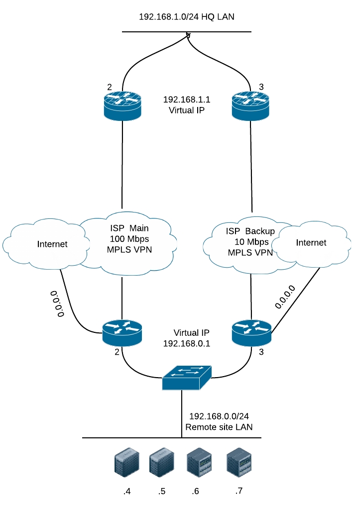
- One HQ site LAN (top of diagram).
- A remote site (bottom of diagram) that has one provider with 2 routers serving as default gateway for the local LAN for high availability.
- The remote network reaches the HQ LAN via MPLS network of the provider. Internet access is done locally on the same router device.
- Internet access is provided through interface FastEthernet4 of the routers and MPLS VPN is provided through the interface Vlan999
Objective:
Provide high availability for both the VPN and Internet access for the remote site.
Equipment used:
We are using for this example two Cisco 881-SEC-K9 routers with c880data-universalk9-mz.150-1.M7.bin image installed.
Configuration of Router 1
Below is the configuration for tracking the VPN line. We will use IP SLA tracking with icmp echo sent via Vlan999 to the HQ router. To be sure we are reaching the LAN in HQ we will track it’s gateway virtual IP.
ip sla 1
icmp-echo 192.168.1.1 source-interface Vlan999
timeout 9000 <————- the time configured , in milliseconds, that the router waits for a response
frequency 15 <—————- sends probes every 15 seconds
track 1 ip sla 1 reachability
Below is the configuration for tracking the internet line. Again we will use IP SLA tracking with icmp echo sent via FastEthernet4 to the internet.
ip sla 2
icmp-echo 100.100.100.100 source-interface FastEthernet4
timeout 9000 <———–the time configured , in milliseconds, that the router waits for a response
frequency 15 <—————– sends probes every 15 seconds
ip sla schedule 2 life forever start-time now
track 2 ip sla 2 reachability
NOTE: The example address 100.100.100.100 shown above is the internet IP monitored. It can be your ISP default gateway or any other IP from the internet that sends icmp reply. Be careful because public services or providers can have ICMP blocked on their equipment and some pings may fail.
Below is the tracking configuration with boolean object tracking so that if any of the IP SLA tracking mechanisms fail, the standby router will become active.
track 3 list boolean and
object 1 < —————— track 1
object 2 <—————— track 2
After tracking is configured we can configure the HSRP on Vlan1. Assume that Vlan1 is the vlan facing the LAN of the two routers.
interface Vlan1
ip address 192.168.0.2 255.255.255.0
standby 1 ip 192.168.0.1 <———- Virtual HSRP IP Address
standby 1 priority 150 <———- Configured priority
standby 1 preempt <———– Preemption required to be enabled
standby 1 track 3 decrement 60 <———– If the tracking list is down the priority decrements by 60, becomes 90 which is under 100, and the router switches to standby mode
Some verifications are required to see if everything is working properly
Cisco@Networkstraining# show track 3
Track 3
List boolean and
Boolean AND is Up
1 changes, last change 1d10h
object 1 Up
object 2 Up
Tracked by:
HSRP Vlan1 1
NOTE: if any of the two objects goes down, track 3 goes down also. If I would have configured using the OR boolean statement, then for track 3 to go down both of the objects must go down.
Cisco@Networkstraining#show standby vlan 1 brief
P indicates configured to preempt.
|
Interface Grp Pri P State Active Standby Virtual IP
Vl1 1 150 P Active local 192.168.0.3 192.168.0.1
Configuration of Router 2 is done in the same way, the only difference is that the priority is left default (100).
There are many applications for IP SLA monitoring with object tracking. Other network redundancy examples will be covered in future articles.
Related Posts
- How to Configure Port Forwarding on Cisco Router (With Examples)
- Redistribution and OSFP – Discussion With Cisco Commands Examples
- Cisco HSRP States and Troubleshooting (With Commands)
- Cisco Router Login – GUI Login and How to Secure Your Access
- Route Filtering and OSPF – Workaround With Distribute List Filtering