One of the concepts involved with the EIGRP routing protocol that can sometimes be confusing is the idea of the feasible distance and the reported distance of a particular network destination.
Understanding these two measurements of EIGRP is an important step in understanding some of the fundamental mechanisms of EIGRP.
Definition of Terms
Let’s start by stating the definition of each of these measurements. Once this is done, we will dig deeper to further understand their meaning and usefulness by examining a related topology and a step-by-step progression of the EIGRP process.
To understand these definitions, we must first clarify that these measurements are different based on which router’s point of view we are taking into account.
Having this in mind, let’s state our definitions as follows:
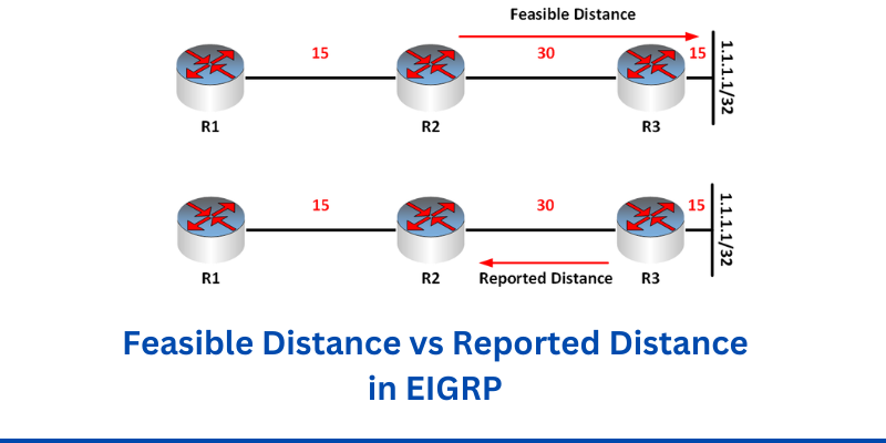
The feasible distance is the metric to the destination from the point of view of the local router.
The reported distance is the metric to the destination that has been reported to the local router by one of its EIGRP neighbors.
Practical EIGRP example
Now let’s see what this actually means using the following EIGRP topology:
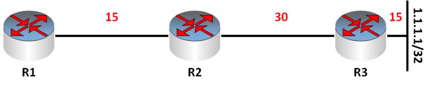
Let’s assume that all three routers have EIGRP enabled, and they have created neighbor adjacencies between them.
The 1.1.1.1/32 network is the destination that will be propagated throughout the topology. The numbers in red are the metric that each link contributes to the path to the destination.
As we said before, the key to understanding these distances is realizing which router’s point of view we are taking into account.
Feasible Distance
From the point of view of R2 the feasible distance to the destination network is the total cost of the path to reach that destination. In this case, it is the following:
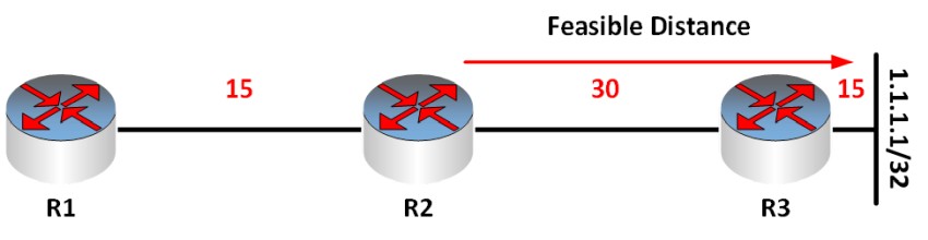
So from the point of view of R2, the feasible distance to the destination network of 1.1.1.1/32 is the sum of the metrics of each link, that is, 30 + 15 = 45.
In this sense, you can see that the feasible distance to a destination from a particular router is simply the sum of the metrics of all of the intervening links of the path.
Reported Distance
To understand the reported, distance, let’s take a look at this diagram:
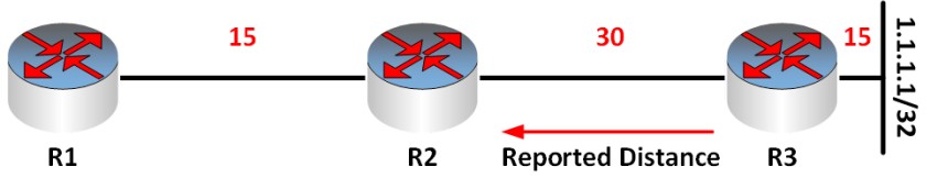
Once again, we are using the point of view of R2. So for the 1.1.1.1/32 destination network, R3 sends an EIGRP update informing R2 that it has a distance to that destination of 15. In other words, an EIGRP neighbor is reporting or informing R2 about its distance to the destination network in question.
In this topology, there is only one reported distance. If there were multiple paths to the destination network then we would also have multiple reported distances to that destination from each EIGRP router.
The reported distance is needed in order for an EIGRP router to determine its own feasible distance. The only way R2 computes its feasible distance of 45, as shown previously, is because it is informed by R3 about its reported distance to the destination.
And since R2 knows that the metric of the link to R3 is 30, it simply adds this value to the reported distance to get that result of 45.
Importance of Feasible and Reported Distance
The feasible distance and the reported distance are important components of one of EIGRP’s best features.
When there are multiple paths to a particular destination, EIGRP places within its topology table a feasible successor. This is just a fancy name for a backup path.
In the event of a failure of the primary path, the backup path is almost instantaneously installed in the routing table, ensuring virtually zero downtime.
While computing this feasible successor, EIGRP uses what is known as a feasibility condition to determine if the backup path is guaranteed to be loop-free. We won’t go into why this condition is used, but we will see how the feasible distance and the reported distance are used to evaluate it.
The feasibility condition states that:
In order for a backup path to be successfully installed, its reported distance must be less than the feasible distance of your best path.
To illustrate this, I’ve added a couple more routers to our topology:
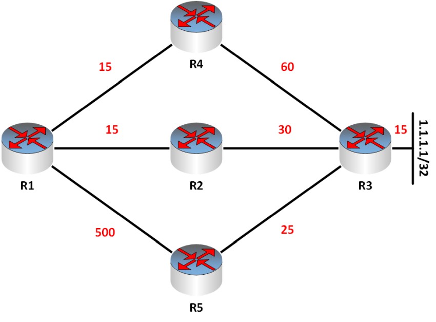
Once again, the red numbers indicate the EIGRP metric of each link. Now, our point of reference is R1, so we’re looking at the network topology from R1’s point of view.
R1 will receive three reported distances, one from R4, R2, and R5. R1 will also compute three feasible distances, one via each of R4, R2, and R5. Here’s a table that summarizes these computed values. See if you can determine how they were derived:
| Path via | Feasible Distance | Reported Distance |
| R4 | 15 + 60 + 15 = 90 | 60 + 15 = 75 |
| R2 | 15 + 30 + 15 = 60 | 30 + 15 = 45 |
| R5 | 500 + 25 + 15 = 540 | 25 + 15 = 40 |
First of all, let’s determine our best path. EIGRP calls that path the “successor.” This is simply the path with the lowest feasible distance. That would be our path via R2, which has a metric of 60.
Now you would assume that the backup path would be the path with the next highest feasible distance. That should be via R4 which has a feasible distance of 90. However, we must first check the feasibility condition. Remember once again, we’re looking at the problem from the point of view of R1.
What’s the reported distance of R4 on that path? It’s 75. What’s the feasible distance of our best path? 60. The reported distance must be less than the best path metric. However, 75 is not less than 60, therefore this path cannot be used as the backup path.
Let’s check the feasibility condition of our path via R5. What’s the reported distance of R5? It’s 40. What’s the feasible distance of our best path? 60. The reported distance of 40 is less than 60 which is the feasible distance of our best path, thus the condition is met. Here’s the table again showing the resulting best path and the backup path.
| Path via | Feasible Distance | Reported Distance | Path |
| R4 | 15 + 60 + 15 = 90 | 60 + 15 = 75 | |
| R2 | 15 + 30 + 15 = 60 | 30 + 15 = 45 | Best path |
| R5 | 500 + 25 + 15 = 540 | 25 + 15 = 40 | Feasible Successor (backup path) |
Conclusion
From the above description, you can see the important role that the feasible distance and the reported distance play in the operation of EIGRP.
It is important to always remember the frame of reference you are using, that is, which router’s point of view you are performing the computations from.
If you maintain that point of reference firmly in your mind, it will be much easier to understand these distances and the role they play in EIGRP.
Related Posts
- Redistribution and OSFP – Discussion With Cisco Commands Examples
- EIGRP Variance and Unequal Cost Load Balancing in Networking
- Explanation and Comparison of OSPF E1 vs E2 Routes
- Discussion and Explanation of OSPF Graceful Restart and Shutdown
- Explanation and Configuration of OSPF MD5 Authentication on Cisco Networks