Throughout my professional career in networking I was lucky to work with all Cisco firewall models and therefore I have experienced the “evolution” of every firewall product developed by Cisco.
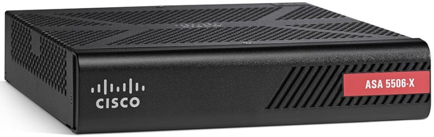
For the SMB/SOHO market, Cisco’s initial offering was the PIX 501, followed by the successful Cisco ASA 5505. The latter came to an End-of-Sale in 2014 and now the replacement low-end model is the new Cisco ASA 5506-X.
One of the most popular configuration guides on this blog is this basic ASA 5505 tutorial . Since these are useful posts for many people, I’ve decided to write also a configuration tutorial for the new ASA 5506-X.
I will cover two popular use cases of the 5506-X. One is a simple scenario of providing internet access to an internal LAN. The second case is more advanced and will cover two DMZ zones, one with a publicly accessible Web Server and one with a Guest WiFi Access Point.
Cisco ASA 5506-X Specs and Features
Before starting the discussion on how to configure the 5506, let’s first see the most important specs and features of this model.
- It comes in two hardware “flavors”, the normal 5506-X and also the 5506W-X which has an integrated wireless access point (a/b/g/n bands).
- It comes in two software license “flavors”, the Base License and the Security Plus License.
- 8x1GE Network Interfaces (these are routed ports, not switch ports like the previous 5505 model).
- 1 Management Interface (for the FirePOWER module).
- Performance throughput varies according to what services are enabled. 300 Mbps for only firewall services, 250 Mbps for Application Visibility and Control (AVC), 125 Mbps for Application Control (AVC) and IPS/NGIPS, 100 Mbps for VPN throughput.
- Max 20,000 concurrent sessions with the Base License or 50,000 with the Sec.Plus License.
- 5 VLANs with Base License and 30 with the Security Plus License.
- 10 IPSEC Site-to-Site VPNs (Base License) and 50 VPNs with Sec. Plus.
- Unlimited internal hosts (even with the Base License).
- Active/Standby high availability (only with Security Plus License).
- Comes with FirePOWER Services (Application Visibility and Control – AVC) which supports more than 3000 application-layer and risk-based controls.
- With extra subscription cost you can have also Next Generation IPS, Advanced Malware Protection and URL filtering.
Note Regarding Licenses and Subscriptions:
You should contact your local reseller and ask about License cost, “right-to-use” subscriptions needed etc. They made licensing too complex in my opinion so you must conduct your reseller for more details and to avoid any “surprises”. For example, Anyconnect needs extra license, IPS requires subscription etc.
How to connect the ASA 5506-X in your network for Initial Configuration
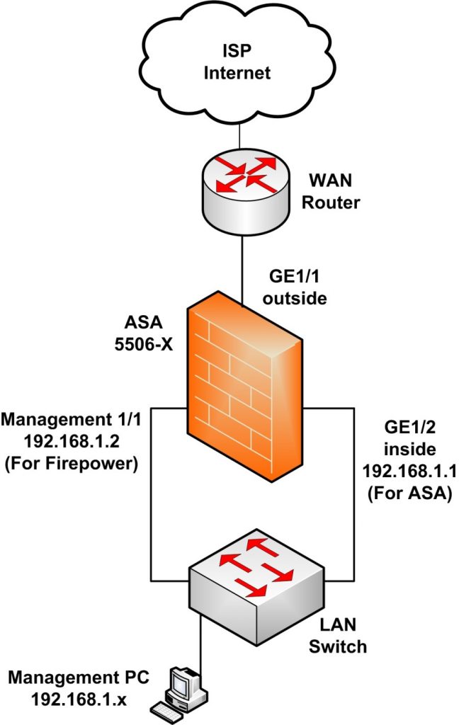
As you can see in the specs section above, there are 8x1G network interfaces and also one Management interface (Management 1/1) which belongs to the FirePOWER module. In order to deploy the device in your network and be able to start its initial configuration, connect it as following:
NOTES:
- The Management 1/1 interface belongs to the separate FirePOWER module and NOT to the ASA.
- DO NOT configure an IP address for the Management 1/1 interface inside the ASA configuration.
- The default “inside” IP address for managing the ASA is 192.168.1.1 (interface GE1/2).
- You must configure an IP address for Management1/1 in the 192.168.1.x subnet (e.g 192.168.1.2) inside the FirePOWER module (or via the ASDM GUI as we’ll see below).
- You must connect both GE1/2 (inside) and Management1/1 interfaces on the same Layer2 LAN switch.
- The outside interface (GE1/1) must be connected to the WAN (ISP) device and will receive IP address dynamically by default (via DHCP).
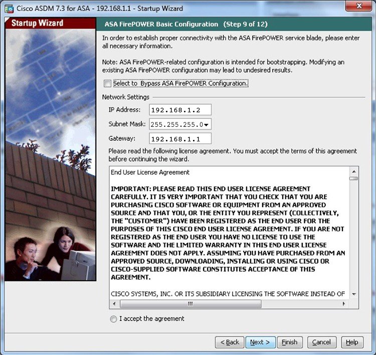
- The quickest way to manage initially the device is using ASDM. Launch a web browser on your Management PC and go to https://192.168.1.1/admin. Select “Startup Wizard”, leave username/password fields empty and hit OK.
- When the wizard takes you to the FirePOWER network settings, enter IP address 192.168.1.2, Mask 255.255.255.0 and Gateway 192.168.1.1 (see below).
- After you finish the above, quit the ASDM application and then relaunch it. This time you will see new FirePOWER tabs on the GUI home page which means you can now configure also FirePOWER settings in addition to ASA settings.
ASA 5506-X Basic Configuration Tutorial
The ASA 5506-X has a default configuration out-of-the-box. This default configuration has the following characteristics:
- Internal LAN: 192.168.1.0/24
- Internal LAN can access the Internet.
- The WAN (outside) interface (GE1/1) is configured to receive IP address from DHCP.
- The LAN (inside) interface (GE1/2) has IP address 192.168.1.1
- DHCP is enabled for providing IP address to internal hosts.
In this section we will describe how to change this default configuration to suit your network topology. We assume that you already have network connectivity (or console connectivity) to the device so that you can start configuring with Command Line Interface (CLI).
This is our network topology for the basic configuration.
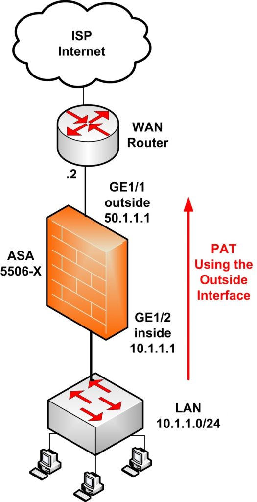
- Internal user LAN: 10.1.1.0/24
- ASA inside IP: 10.1.1.1
- ASA outside IP (static): 50.1.1.1
- NAT: Dynamic overload (PAT) using the outside interface.
Step 1: Configure the Internal LAN interface
description LAN
nameif inside
security-level 100 <- Security level 100 means it’s the most trusted interface
ip address 10.1.1.1 255.255.255.0
no shut
Step 2: Configure the Outside WAN interface
description WAN
nameif outside
security-level 0 <- Security level 0 means it’s the least trusted interface
ip address 50.1.1.1 255.255.255.0 <- Assume we have a static public IP from the ISP
no shut
NOTE:
In case the outside interface will receive IP address dynamically via DHCP use this command:
Step 3: Configure PAT using the outside interface
Step 4: Configure default route towards the ISP (assume default gateway is 50.1.1.2)
OPTIONAL STEPS (But Useful)
Step 5: Assign IP addresses via DHCP to internal hosts
You can configure the ASA to work as DHCP server and assign IP addresses dynamically to internal hosts.
dhcpd dns 208.67.220.220 208.67.222.222 <- ASA will assign DNS servers (these are the opendns by the way)
dhcpd enable inside
Step 6: Enable SSH access for management
crypto key generate rsa modulus 1024
ssh 10.1.1.5 255.255.255.255 inside <- Allow SSH access only from inside host 10.1.1.5
aaa authentication ssh console LOCAL <- Enable local authentication for SSH
username admin password [STRONGPASS] privilege 15
enable password Gh4w7$-s39fg#(!
Step 7: Apply useful ACL on outside
I usually apply the following ACL on the outside interface. It has two purposes: First is to allow ICMP reply packets to come back in (when pinging from inside to outside) and second purpose is to log any denied packets hitting the firewall from outside (for alert and security purposes).
access-list OUTSIDE-IN extended deny ip any any log
access-group OUTSIDE-IN in interface outside
The above concludes the basic configuration of the ASA 5506-X. Next we will see a more advanced scenario with web server and guest WiFi in two DMZ zones.
ASA 5506-X Configuration with two DMZ Networks
This is also a popular scenario found in many corporate networks. We have two DMZ segments (DMZ1 and DMZ2) which accommodate a Web Server (DMZ1) and Guest WiFi Access Point (DMZ2). Of course, there is also the “inside” zone which hosts the internal users and also the “outside” zone connected to Internet.
Have a look at the diagram below for better illustrating the use case we will discuss.
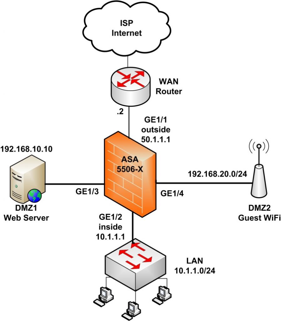
Network Requirements:
- LAN will be able to access the Internet, DMZ1 and DMZ2.
- DMZ1 will be able to access the Internet but not the inside zone.
- DMZ2 will be able to access the Internet but not the inside zone.
- The Guest WiFi Access Point will assign IPs to wireless clients in the range 192.168.20.0/24 and will provide Internet access to these clients.
- The Web Server (192.168.10.10) will be accessible from the Internet at port 80.
- Assume that we have only 1 public IP address assigned from our ISP (static IP). This is the IP address configured on the ASA outside interface (50.1.1.1). Therefore, the Web Server will be accessible using this static public IP using “port redirection”. Traffic from Internet hitting the outside interface IP (50.1.1.1) on port 80 will be redirected to the Web Server private IP 192.168.10.10
Configuration
Let’s now see the configuration of the scenario above:
Step 1: Configure the Interfaces
description LAN
nameif inside
security-level 100 <- Security level 100 means the most trusted interface
ip address 10.1.1.1 255.255.255.0
no shut
interface GigabitEthernet1/1
description WAN
nameif outside
security-level 0 <- Security level 0 means the least trusted interface
ip address 50.1.1.1 255.255.255.0
no shut
interface GigabitEthernet1/3
description Web Server DMZ1
nameif DMZ1
security-level 50 <- Choose Security level between 1-99
ip address 192.168.10.1 255.255.255.0
no shut
interface GigabitEthernet1/4
description WiFi DMZ2
nameif DMZ2
security-level 40 <- Choose Security level between 1-99
ip address 192.168.20.1 255.255.255.0
no shut
Step 2: Configure NAT Overload
nat (inside,DMZ1) after-auto source dynamic any interface
nat (inside,DMZ2) after-auto source dynamic any interface
nat (DMZ1,outside) after-auto source dynamic any interface
nat (DMZ2,outside) after-auto source dynamic any interface
The above configures NAT overload (PAT) in order to have traffic flow from higher security levels to lower security levels.
This means that the “inside” network will have access to all other networks (DMZ1, DMZ2, outside). Also, DMZ1 (security level 50) will have access to “outside” and to DMZ2 (security level 40). Finally, DMZ2 will have access only to “outside”.
Step 3: Configure static NAT (port redirection) and ACL to access Web Server
host 192.168.10.10
nat (DMZ1,outside) static interface service tcp www www
access-list OUT_IN extended permit tcp any host 192.168.10.10 eq www <- See NOTE2
access-group OUT_IN in interface outside
NOTE1:
The above static NAT configures PORT Redirection for host 192.168.10.10 (Web Server) using the outside interface. Any traffic hitting the outside interface (50.1.1.1) on port 80 will be redirected to 192.168.10.10 on port 80.
If you have a dedicated static IP for the Web Server (assume 50.1.1.3 is dedicated for the Web Server), the static NAT will be:
object network WEB_SRV
host 192.168.10.10
nat (DMZ1,outside) static 50.1.1.3 service tcp www www
NOTE2:
The static NAT configured before is not enough to allow access to the Web Server. An ACL is also needed on the outside interface. The above ACL allows TCP port 80 from “any” source to access the Web Server IP (192.168.10.10).
Step 4: Configure default route towards the ISP (assume default gateway is 50.1.1.2)
The above configuration shows the minimum essential commands needed to satisfy our network requirements. You need of course to implement more features such as SSH access, enable logging, time settings, FirePOWER configuration etc but these are not in the scope of this article.
I hope you will find the above helpful for configuring the new ASA 5506-X firewall. For any questions, let me know in the comments below.
DOWNLOAD TUTORIAL HERE
Related Posts
- Prevent Spoofing Attacks on Cisco ASA using RPF
- Configuring Connection Limits on Cisco ASA Firewalls – Protect from DoS
- Configuring AAA Authentication-Authorization-Accounting on Cisco ASA Firewall (TACACS+, RADIUS)
- Cisco ASA Firewall Management Interface Configuration (with Example)
- How to Configure Access Control Lists on a Cisco ASA 5500/5500-X Firewall (with Examples)