We know that a Layer 2 VLAN is an isolated Broadcast Domain and for communicating between VLANs a Layer 3 Device is required (either router or Layer3 switch) for inter-VLAN Routing.
A Private VLAN gives us the opportunity to divide a VLAN into Sub VLANs. In the case of PVLAN, a normal Layer 2 VLAN is mapped on Secondary VLANs. This helps us to restrict devices being connected in the same normal VLAN (subnet) to communicate with each other. Catalyst 3560 and higher models support PVLAN.
Often PVLANs are used in cases where servers are located in a DMZ on the same Layer2 Vlan and we want to restrict these servers to communicate between them.
This helps a lot in security. If the servers are publicly accessible from the Internet, when one of the servers is compromised by hackers, we can block the attacker to access the other servers on the same Vlan.
Of course we can do this with a L3 device or firewall, but in this case each server should have it’s own VLAN/subnet and as a result we’ll get a complex network. In the case of PVLAN, we’ll have one network (VLAN and Layer3 subnet) and we’ll restrict the connection between servers in Layer2 level by creating secondary VLANs.
Private VLAN Types and Port Types:
VLAN Types
The logic behind private VLANs is simple: There is a “normal” VLAN that is known as Primary which has associated secondary VLANs. The secondary VLANs can be either Isolated or Community type:
- Primary: This is the main vlan and carries traffic from the secondary isolated and community vlans.
- Isolated: which means that any switch ports associated with the isolated vlan can reach only the primary vlan and are unable to communicate with any other isolated hosts or devices in other private or community vlans.
- Community: which means that ports associated with a community vlan can communicate with each other and the primary vlan, but not with any other private vlans.
Port Types
Promiscuous (P): Usually connects to a router (Default gateway) and also to span port – a type of a port which is allowed to send and receive frames from any other port on the Primary VLAN.
Isolated (I): This type of port is only allowed to communicate with P-ports – they are “stub”. This type of port usually connects to hosts. Only one isolated VLAN is created. The ports, which are in isolated VLAN, can NOT communicate with each other therefore providing complete isolation of hosts even if they belong to the same Layer2 vlan.
Community (C): The ports in the same Community can communicate with each other and also are connected to Promiscuous port. There are multiple Communities available.
Community ports are allowed to talk to their buddies, sharing the same group (of course they can talk to P-ports).
Let’s see how to configure PVLANs
Equipment Used in this LAB:
Cisco Catalyst 3560 – C3560-IPSERVICES-M Version 12.2(50)SE
Cisco Router 2801 – C2801-ADVIPSERVICESK9-M Version 12.4(9)T4
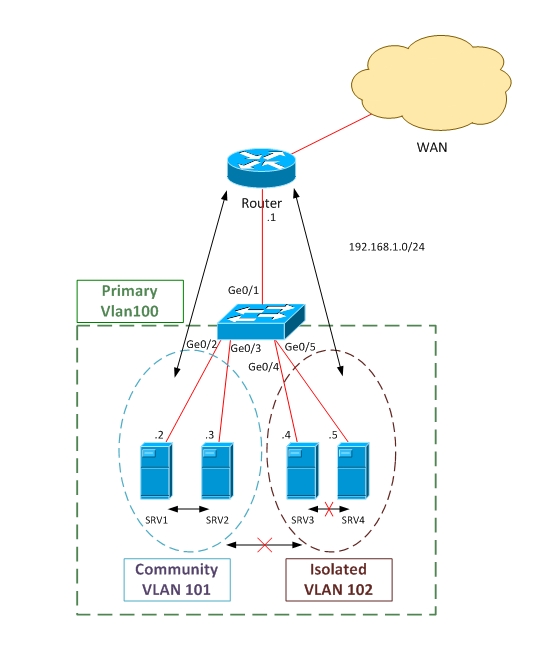
Scenario: Create one Community VLAN (101), in which SRV1 and SRV2 will belong to. Create also an Isolated VLAN (102), in which SRV3 and SRV4 will belong to. Make Ge0/1 Promiscuous and connect to default gateway (router or firewall).
According to this configuration, SRV1 and SRV2 can talk to each other and also with Router (Default Gateway). On the other hand, Servers in Isolated VLAN (SRV3 and SRV4) will not communicate between each other and also will not be able to talk with the Community vlan (SRV1 and SRV2).
Notice also that the Layer3 subnet for all of the hosts is the same (192.168.1.0/24). This does not matter because the restrictions in communication will be imposed by the switch on Layer2 level.
Before starting PVLAN configuration, switching VTP Mode to Transparent is required. If VTP works in other mode, PVLAN will not work.
!switch to Transparent mode
Switch(config)# vtp mode transparent
Setting device to VTP TRANSPARENT mode.
!Create Isolated VLAN
Switch(config)# vlan 102
Switch(config-vlan)# private-vlan isolated
!create community vlan
Switch(config)# vlan 101
Switch(config-vlan)#private-vlan community
!Create Primary VLAN and map with secondary vlans
Switch(config-vlan)# vlan 100
Switch(config-vlan)# private-vlan primary
switch(config-vlan)# private-vlan association 101 102
Our Complete Configuration looks Like This:
vlan 100
private-vlan primary
private-vlan association 101 102
!
vlan 101
private-vlan community
vlan 102
private-vlan isolated
! Create promiscuous port and map with the other vlans
Switch(config)# interface ge0/1
Switch(config-if)# switchport mode private-vlan promiscuous
Switch(config-if)# switchport private-vlan mapping 100 101 102
! association of Ge0/2 and Ge0/3 ports with Primary and Secondary VLANS. According to our scenario Ge0/2 and Ge0/3 should be in community Vlan.
Switch(config)# interface range ge0/2-ge0/3
Switch(config-if)# switchport mode private-vlan host
Switch(config-if)# switchport private-vlan host-association 100 101
! association Ge0/4 and Ge0/5 ports with Primary and Secondary VLANS. According to our !scenario Ge0/4 and Ge0/ should be in Isolated Vlan.
Switch(config)# interface range ge0/4-ge0/5
Switch(config-if)# switchport mode private-vlan host
Switch(config-if)# switchport private-vlan host-association 100 102
Configuration is completed now so let’s see how the output looks like.
Switch# show interface status
Port Name Status Vlan Duplex Speed Type
Gi0/1 connected 100 a-full a-100 10/100BaseTX
Gi0/2 connected 100,101 a-full a-100 10/100/0BaseTX
Gi0/3 connected 100,101 a-full a-100 10/100BaseTX
Gi0/4 connected 100,102 a-full a-100 10/100BaseTX
Gi0/5 connected 100,102 a-full a-100 10/100BaseTX
In a future tutorial a different method to separate client’s traffic will be presented using VRF Lite.
Related Posts
- What is Cisco Switch Virtual Interface (SVI) – Configuration Example and Explanation
- Deleting the VLAN Database from a Cisco Switch (IOS or Nexus)
- What is Cisco Virtual Port Channel (vPC) – Explained and Discussed
- Discussion and Explanation of BPDU Guard (With Cisco Config Example)
- From Reactive to Proactive: Mastering Network Performance with Switch Monitoring