We have two types of IPSEC VPNs: Lan-to-Lan (or site-to-site) encrypted VPN and Remote Access VPN.
The first one is extensively used to securely connect distant office networks and the second one for allowing remote users/teleworkers to access resources on a central site network.
In this post we will describe briefly a Lan-to-Lan IPSEC VPN and provide a full configuration example with two Cisco IOS Routers using IPSEC. Have in mind also that site-to-site IPSEC VPN can also be configured on Cisco ASA firewalls as I have described here.
With IPSEC VPNs, businesses can connect together remote office LANs over the Internet with the strong encryption and security offered by the IPSEC protocol.
IPSEC is an IETF security standard. It is basically a suit of several protocols that offer secure communication over insecure paths.
It is therefore ideal for connecting securely distant LAN networks over the insecure Internet. We could use a private WAN network with Frame Relay or MPLS connections, which however would bring the cost very high. Another modern option of course is to use an SD-WAN technology which again uses the public Internet for reduced cost.
Instead, with IPSEC VPN we can use cheap Internet connectivity (which will be secured by IPSEC) for communication between our remote sites.
Network Diagram
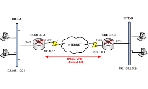
We will be using the example diagram above for the configuration scenario. Generally, there are two Phases for IPSEC VPN:
- Phase 1: In this Phase we configure an ISAKMP policy. This policy establishes an initial secure channel over which further communication will follow. It defines how the ipsec peers will authenticate each other and what security protocols will be used.
- Phase 2: In this Phase we configure a crypto map and crypto transform sets. In general, Phase 2 deals with traffic management of the actual data communication between sites. The transform sets configured here, define what authentication and encryption protocols will be used on the data traffic.
Configuration Example
For IPSEC site-to-site VPN configuration check out the following example. One important point to keep in mind is NAT configuration.
In most real networks, the border router which connects the site to the Internet is used also for terminating the IPSEC VPN tunnel.
This border router must also perform NAT in order to provide access to the private LAN IP addresses to the Internet.
However, IPSEC does not work with NAT. Therefore, we need to create a NAT exemption rule for the traffic going from Site1 to Site2 (and vica-versa) in order to disable NAT for the traffic which is going to pass through the IPSEC tunnel.
Let’s see the complete configurations for ROUTER-A and ROUTER-B below:
Configuration of Cisco ROUTER-A:
ROUTER-A#show run
Building configuration…
version 12.3
service timestamps debug datetime msec
service timestamps log datetime msec
no service password-encryption
!
hostname ROUTER-A
!
boot-start-marker
boot-end-marker
!
!
!
ip audit po max-events 100
no ip domain lookup
no ftp-server write-enable
!
!— Define Internet Key Exchange (IKE) policy.
crypto isakmp policy 10
!— Specify the 256-bit AES as the
!— encryption algorithm within an IKE policy.
encr aes 256
!— Specify that pre-shared key authentication is used.
authentication pre-share
!— Specify the shared secret.
crypto isakmp key testkey1234 address 200.0.0.1
!
!
!— Define the IPSec transform set.
crypto ipsec transform-set aes-sha-transform esp-aes 256 esp-sha-hmac
!
!— Define crypto map entry name “aesmap” that will use
!— IKE to establish the security associations (SA).
crypto map aesmap 10 ipsec-isakmp
!— Specify remote IPSec peer.
set peer 200.0.0.1
!— Specify which transform sets
!— are allowed for this crypto map entry.
set transform-set aes-sha-transform
!— Name the access list that determines which traffic
!— should be protected by IPSec.
match address acl_vpn
!
interface FastEthernet0/0
ip address 100.0.0.1 255.255.255.0
ip nat outside
!— Apply crypto map to the outside interface.
crypto map aesmap
!
interface FastEthernet0/1
ip address 192.168.1.254 255.255.255.0
ip nat inside
ip nat inside source list acl_nat interface FastEthernet0/0 overload
ip classless
ip route 0.0.0.0 0.0.0.0 100.0.0.2
no ip http server
no ip http secure-server
!
ip access-list extended acl_nat
!— Exclude protected traffic from being NAT’ed.
deny ip 192.168.1.0 0.0.0.255 192.168.2.0 0.0.0.255
permit ip 192.168.1.0 0.0.0.255 any
!— Access list that defines traffic protected by IPSec.
ip access-list extended acl_vpn
permit ip 192.168.1.0 0.0.0.255 192.168.2.0 0.0.0.255
!
!
line con 0
exec-timeout 0 0
line aux 0
line vty 0 4
!
end
Configuration of Cisco ROUTER-B:
ROUTER-B#show run
Building configuration…
version 12.3
service timestamps debug datetime msec
service timestamps log datetime msec
no service password-encryption
!
hostname ROUTER-B
!
boot-start-marker
boot-end-marker
!
ip audit po max-events 100
no ip domain lookup
no ftp-server write-enable
!
!— Define Internet Key Exchange (IKE) policy.
crypto isakmp policy 10
!— Specify the 256-bit AES as the
!— encryption algorithm within an IKE policy.
encr aes 256
!— Specify that pre-shared key authentication is used.
authentication pre-share
!— Specify the shared secret.
crypto isakmp key testkey1234 address 100.0.0.1
!
!
!— Define the IPSec transform set.
crypto ipsec transform-set aes-sha-transform esp-aes 256 esp-sha-hmac
!
!— Define crypto map entry name “aesmap” that will use
!— IKE to establish the security associations (SA).
crypto map aesmap 10 ipsec-isakmp
!— Specify remote IPSec peer.
set peer 100.0.0.1
!— Specify which transform sets
!— are allowed for this crypto map entry.
set transform-set aes-sha-transform
!— Name the access list that determines which traffic
!— should be protected by IPSec.
match address acl_vpn
!
interface FastEthernet0/0
ip address 200.0.0.1 255.255.255.0
ip nat outside
!— Apply crypto map to the outside interface.
crypto map aesmap
!
interface FastEthernet0/1
ip address 192.168.2.254 255.255.255.0
ip nat inside
ip nat inside source list acl_nat interface FastEthernet0/0 overload
ip classless
ip route 0.0.0.0 0.0.0.0 200.0.0.2
no ip http server
no ip http secure-server
!
ip access-list extended acl_nat
!— Exclude protected traffic from being NAT’ed.
deny ip 192.168.2.0 0.0.0.255 192.168.1.0 0.0.0.255
permit ip 192.168.2.0 0.0.0.255 any
!— Access list that defines traffic protected by IPSec.
ip access-list extended acl_vpn
permit ip 192.168.2.0 0.0.0.255 192.168.1.0 0.0.0.255
!
!
line con 0
exec-timeout 0 0
line aux 0
line vty 0 4
!
end
Related Posts
- How to Configure Port Forwarding on Cisco Router (With Examples)
- Redistribution and OSFP – Discussion With Cisco Commands Examples
- Cisco HSRP States and Troubleshooting (With Commands)
- Cisco Router Login – GUI Login and How to Secure Your Access
- Route Filtering and OSPF – Workaround With Distribute List Filtering