Networks Training

  • About
  • My Books
  • SUGGESTED TRAINING
  • HOME
  • Cisco Networking
    • Cisco General
    • Cisco IOS
    • Cisco VPN
    • Cisco Wireless
  • Cisco ASA
    • Cisco ASA General
    • Cisco ASA Firewall Configuration
  • Certifications Training
    • CCNA Training
    • Cisco Certifications
    • I.T Training
  • General
    • General Networking
    • IP Telephony
    • Network Security
    • Product Reviews
    • Software
  • Cisco Routers
  • Cisco Switches
You are here: Home / Cisco General / How to Configure Cisco SPAN – RSPAN – ERSPAN (With Configuration Commands)

How to Configure Cisco SPAN – RSPAN – ERSPAN (With Configuration Commands)

Written By Harris Andrea

Having visibility in the traffic flowing through your network from specific hosts is an excellent way to troubleshoot problems or gather useful information and data.

Cisco switches offer the capability to copy packets from specific ports or VLANs and send them to other ports for capturing and analyzing.

cisco span rspan

The traffic can be captured and analyzed using for example Wireshark. This is also useful when you want to send traffic to an Intrusion Detection System (IDS) for security purposes.

In Cisco environments you can use a feature called SPAN (Switch Port Analyzer) for this purpose.

There are three kinds of SPAN modes that are available for different scenarios: SPAN, RSPAN & ERSPAN all of them having the following key features:

  • Require a source port or vlan and a destination port where the traffic will be collected.
  • Source port can be a routed port, switchport, trunk or etherchannel.
  • Destination port does not support 802.1x, private vlan, CDP, STP, VTP.

Something to keep in mind also is that you can monitor three kinds of traffic:

  1. Incoming (rx) – monitored traffic is sent towards the destination port before any policy modification (ACL, QoS, Policy-Map etc)
  2. Transmitting (tx) – monitored traffic is sent towards the destination port after any policy is applied.
  3. Encapsulation replicate – Forwards CDP,STP,VTP traffic that usually is ignored by SPAN.

Basic SPAN configuration

For Network Engineers, the ability to mirror switch traffic and send it to a sniffer for analysis is an essential troubleshooting technique.

All Cisco Catalyst switches support the Switched Port Analyzer (SPAN) feature which copies traffic from specified switch source ports or VLANs and mirrors this traffic to a specified destination switch port (SPAN port).

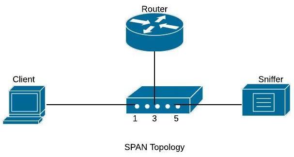
Then, you can connect your PC having a sniffer tool (like WireShark) on the destination SPAN port to capture all mirrored traffic. The diagram below shows this:

MORE READING:  Cisco ASA 5500 new software 8.2 released

Basic SPAN captures traffic from one source port or VLAN and sends the traffic to another port on the same switch.

On the diagram shown below, we will capture traffic from source port fa0/1 (connected to a user computer) and send the traffic to destination port fa0/5.

cisco-span-configuration

Configuration Commands

Switch# configure terminal
Switch(config)# monitor session 1 source interface fa0/1
Switch(config)# monitor session 1 destination interface fa0/5

With this simple configuration, traffic sourced from interface fa0/1 will be mirrored to interface fa0/5 where you will be able to capture it.

We can also monitor the traffic of a whole Vlan and send a copy of the traffic to a destination physical port as shown below:

Configuration Example – Monitoring an entire VLAN traffic

c3750(config)#monitor session 1 source vlan 5
c3750(config)#monitor session 1 destination interface fastethernet 0/5

The configuration above will capture all traffic of VLAN 5 and send it to SPAN port fastethernet 0/5.

Use the command show monitor session 1 to verify your configuration.

Basic RSPAN configuration

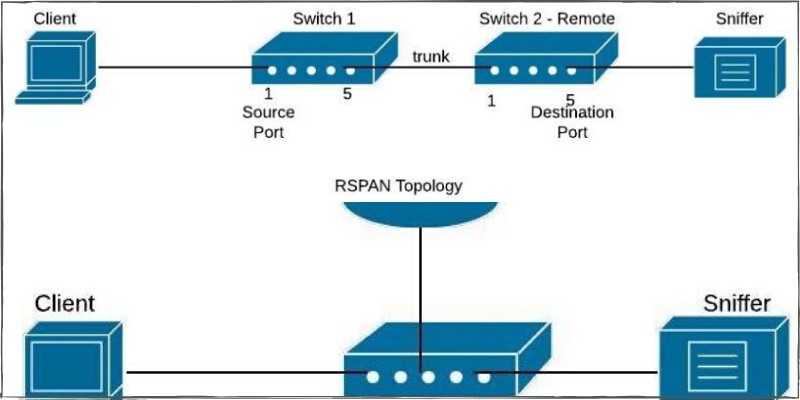
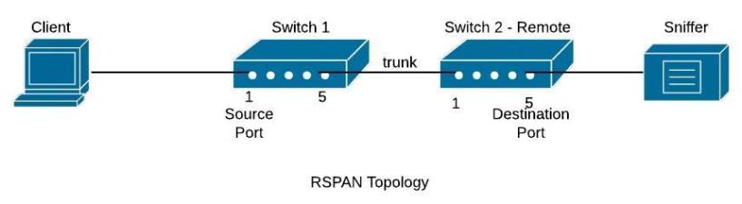
RSPAN (Remote SPAN) feature allows traffic that is sourced from a switch to be mirrored to a remote switch within a layer 2 network over trunk ports. To accomplish this you will have to configure the destination VLAN across the entire path between the switches.

In the diagram below, we want to capture traffic from Switch1 (port fa0/1) and send the traffic to Switch2 (port fa0/5).

Although here we show a direct connection with a Layer2 trunk port between Switch1-Switch2, you can have multiple switches between them with no problem (the capturing vlan must be active on the whole path though).

cisco-rspan-configuration

Configuration Commands

Switch1# config term
Switch1 (config)# vlan 100     < —This is the capturing VLAN
Switch1 (config-vlan)# remote span  
Switch1(config-vlan)# exit
Switch1 (config)# monitor session 10 source interface fa0/1
Switch1 (config)# monitor session 10 destination remote vlan 100Switch2_Remote# config term
Switch2_Remote (config)# vlan 100 < —This is the capturing VLAN
Switch2_Remote (config-vlan)# remote span
Switch2_Remote (config-vlan)# exit
Switch2_Remote (config)# monitor session 11 source remote vlan 100
Switch2_Remote (config)# monitor session 11 destination interface fa0/5

All traffic sourced from interface fa0/1 on switch 1 will be forwarded using vlan 100 towards the destination port on remote switch2 where you can sniff the traffic.

MORE READING:  Where to Buy Refurbished & Used Cisco Equipment (Switches, Routers etc)

Basic ERSPAN configuration

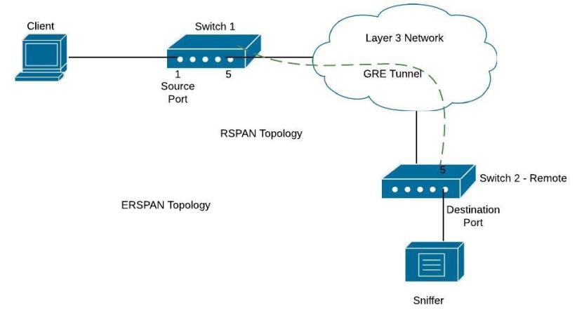
ERSPAN (Encapsulated Remote Switched Port Analyzer) is a feature present on the new IOS-XE on ASR1000 but is also available on Catalyst 6500 or 7600. It is used to send traffic for sniffing over layer3 networks and it works by encapsulating the traffic using a GRE tunnel.

On the diagram below, there is a GRE tunnel between Switch1 (again this is usually an ASR1000 or 7600 etc) and remote Switch2. The GRE tunnel is established between IP address 172.16.10.10 (on switch1) and 10.10.10.10 (on switch2). We want to send traffic from fa0/1 on Switch1 to fa0/5 on Switch2.

cisco-erspan-configuration

Configuration Commands

Switch1

Switch1(config)# monitor session 1 type erspan-source
Switch1 (config-mon-erspan-src)# source interface fa0/1
Switch1 (config-mon-erspan-src)# destination
Switch1 (config-mon-erspan-src-dst)# erspan-id 110 < — This ID must be the same on Switch2
Switch1 (config-mon-erspan-src-dst)# ip address 10.10.10.10 < — ip address on switch2
Switch1(config-mon-erspan-src-dst)# origin ip address 172.16.10.10 < — ip address on switch 1

Switch2

Switch2_Remote (config)# monitor session 1 type erspan-destination
Switch2_Remote (config-mon-erspan-dst)# destination interface fa0/5
Switch2_Remote (config-mon-erspan-dst)# source
Switch2_Remote (config-mon-erspan-dst-src)# erspan-id 110
Switch2_Remote (config-mon-erspan-dst-src)# ip address 10.10.10.10 < — IP address on switch 2

Some final notes:

  • You can monitor specific vlan traffic using the command:

“monitor session 1 source vlan 10”

  • You can monitor incoming or outgoing traffic using

“monitor session 1 source vlan 10 rx/tx”

  • Verification is done issuing:

“show monitor session 1”

DOWNLOAD ARTICLE AS PDF FILE HERE

Related Posts

  • Cisco Command to Test a Copper UTP Ethernet Cable on a Switch
  • What is Cisco Meraki ? Some FAQ About Cisco Meraki You Need to Know
  • What is Cisco Identity Services Engine (ISE)? Use Cases, How it is Used etc
  • Readers Favorite Posts – Articles Liked by our Visitors
  • Cisco IOS Command Line Interface (CLI) Keyboard Shortcuts

Filed Under: Cisco General

Download Free Cisco Commands Cheat Sheets

Enter your Email below to Download our Free Cisco Commands Cheat Sheets for Routers, Switches and ASA Firewalls.

We use Elastic Email as our marketing automation service. By submitting this form, you agree that the information you provide will be transferred to Elastic Email for processing in accordance with their Terms of Use and Privacy Policy. Also, you allow me to send you informational and marketing emails from time-to-time.

About Harris Andrea

Harris Andrea is an Engineer with more than two decades of professional experience in the fields of TCP/IP Networks, Information Security and I.T. Over the years he has acquired several professional certifications such as CCNA, CCNP, CEH, ECSA etc.

He is a self-published author of two books ("Cisco ASA Firewall Fundamentals" and "Cisco VPN Configuration Guide") which are available at Amazon and on this website as well.

Comments

  1. emon says

    July 16, 2015 at 3:21 am

    such a great tutorial . will help all network engineers. Thanks

  2. Harris Andrea says

    July 16, 2015 at 5:38 pm

    Emon,
    I’m glad you liked it.

    Harris

  3. Khem Thapa says

    August 6, 2015 at 6:27 pm

    Nice Explanation.
    Can we configure SPAN and RSPAN for the same session?

  4. Harris Andrea says

    August 6, 2015 at 7:15 pm

    Hi Khem,
    No, you will need to create a different session.

  5. Richard McLoughlin says

    May 3, 2019 at 12:05 pm

    Nice explanation! RSPAN seems a whole lot more simple than I first envisaged.

    Just to confirm I have understood you correctly; in your example for RSPAN, if switch 2 was an intermediate switch as opposed to the last switch the the chain, the only configuration change required is that
    Switch2_Remote (config)# monitor session 11 destination interface fa0/5 would become
    Switch2 (config)# monitor session 11 destination remote vlan 100

  6. Harris Andrea says

    May 3, 2019 at 2:26 pm

    yes that’s correct.

    cheers

    Harris

  7. Ivan says

    June 12, 2019 at 7:48 am

    Hello!

    All ERSPAN destination sessions on a switch must use the same IP address on the same destination interface.

    Settings for ERSPAN are not correct.

    Thanks.

  8. Harris Andrea says

    June 12, 2019 at 8:49 am

    Thanks for your comment.

    This is what I’m showing in the config as well. What is wrong in your opinion?

  9. Ivan says

    June 12, 2019 at 10:55 am

    That is correct article.

    https://community.cisco.com/t5/networking-documents/understanding-span-rspan-and-erspan/ta-p/3144951

    From your article

    Switch2Switch2_Remote (config)# monitor session 1 type erspan-destination
    Switch2_Remote (config-mon-erspan-dst)# destination interface fa0/5
    Switch2_Remote (config-mon-erspan-dst)# source
    Switch2_Remote (config-mon-erspan-dst-src)# erspan-id 110
    Switch2_Remote (config-mon-erspan-dst-src)# ip address 172.16.10.10 < — source IP from switch 1

    Next string is incorrect
    Switch2_Remote (config-mon-erspan-dst-src)# ip address 172.16.10.10 < — source IP from switch 1

    All ERSPAN destination sessions on a switch must use the same IP address on the same destination interface.

    Therefore, it is necessary to write the address in the same from switch 2 – 10.10.10.10

  10. Harris Andrea says

    June 12, 2019 at 1:11 pm

    Ivan after checking again the configuration, you are right that I did a mistake. I have fixed that in the article.
    Thanks a lot

  11. Ivan says

    June 12, 2019 at 10:56 pm

    You are welcome!

  12. Kimtai Antony says

    June 25, 2019 at 8:07 am

    Is it possible to configure this RSPAN over different networks at different geographical locations?

  13. Harris Andrea says

    June 25, 2019 at 12:44 pm

    RSPAN can be configured over Layer2 networks. If the different networks at different geographical locations have Layer2 connectivity between them (e.g over fiber optic) then you can configure RSPAN.

    ERSPAN on the other hand can work over Layer3 networks using GRE

  14. Veera says

    August 13, 2019 at 8:36 am

    Lets say we have 4 switches between Host to sniffer. What is configuration on 3rd and 4th switches?

    Please help

  15. Harris Andrea says

    August 13, 2019 at 8:46 am

    See the section under RSPAN configuration. It says that you need to have the capturing Vlan created in all intermediate switches and running through a trunk port.

  16. Tobias says

    September 2, 2021 at 8:17 am

    Hey Harris,
    thank you very much for this explanation.
    is it possible to configure source vlan into the destination remote vlan, transfer it throw a trunk port to an other switch? On the other switch i would ocnfigure a destination port.
    Like this:

    Coreswitch, where the sniffer is connected to:
    Session 1 (local span session to the sniffer)
    ———
    Type : Local Session
    Source VLANs :
    Both : 1, 2, 3, 4
    Destination Ports : Gi4/0/18
    Encapsulation : Native
    Ingress : Disabled

    Session 2
    ———
    Type : Local Session
    Source VLANs :
    Both : 815
    Destination Ports : Gi4/0/16
    Encapsulation : Native
    Ingress : Disabled

    Remote Switch config:
    Session 1 (all vlans into vlan 815 and transfer ist to the coreswitch)
    ———
    Type : Remote Source Session
    Source VLANs :
    Both : 1-5
    Dest RSPAN VLAN : 815

    Is it possible?

  17. Harris Andrea says

    September 2, 2021 at 1:40 pm

    I didn’t understand exactly what you want to do and why

Leave a Reply

Your email address will not be published. Required fields are marked *

This site uses Akismet to reduce spam. Learn how your comment data is processed.

Search this site

About Networks Training

We Provide Technical Tutorials and Configuration Examples about TCP/IP Networks with focus on Cisco Products and Technologies. This blog entails my own thoughts and ideas, which may not represent the thoughts of Cisco Systems Inc. This blog is NOT affiliated or endorsed by Cisco Systems Inc. All product names, logos and artwork are copyrights/trademarks of their respective owners.

Amazon Disclosure

As an Amazon Associate I earn from qualifying purchases.
Amazon and the Amazon logo are trademarks of Amazon.com, Inc. or its affiliates.

Search

BLOGROLL

Tech21Century
Firewall.cx

Copyright © 2023 | Privacy Policy | Terms and Conditions | Hire Me | Contact | Amazon Disclaimer | Delivery Policy

20 shares