Spanning Tree Protocol (STP) ensures a loop-free topology in a local area network (LAN) made up of switches.
It is desirable to have redundant links in a switched LAN so that a single link failure cannot interrupt normal operation of the network.
But redundant links may also introduce physical switching loops that are undesirable. STP allows to have physical redundancy while preventing loops and associated drawbacks.
Spanning Tree Protocol is standardized as IEEE 802.1D. Cisco introduced several enhancements to the standard STP operation that were later incorporated in Rapid Spanning Tree Protocol (RSTP) defined as IEEE 802.1w.
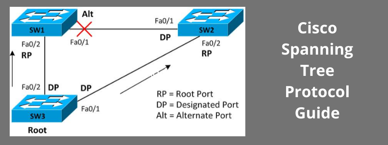
We will focus on Spanning Tree Protocol (STP) configuration and verification commands in this tutorial, as implemented on Cisco switches. Figure 1 shows the topology with three Cisco Catalyst 3550 switches that have been used.
Figure 1 Spanning Tree Protocol on Cisco Switches
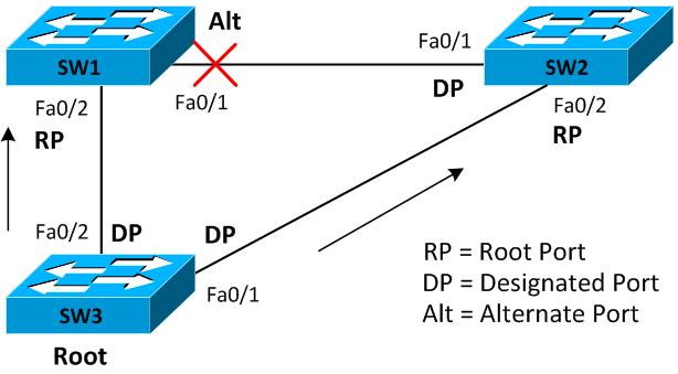
There are three trunk links as shown in Figure 1:
- SW1 Fa0/1 – SW2 Fa0/1
- SW2 Fa0/2 – SW3 Fa0/1
- SW3 Fa0/2 – SW1 Fa0/2
The three switches were interconnected and turned on and without any additional configuration the three trunks were negotiated dynamically by Dynamic Trunking Protocol (DTP). Let’s verify the trunks are successfully established on SW1.
SW1#show interfaces trunk
Port Mode Encapsulation Status Native vlan
Fa0/1 desirable n-isl trunking 1
Fa0/2 desirable n-isl trunking 1
<Output omitted for brevity>
You can use similar commands on SW2 and SW3 to verify successful trunk establishment. Three spanning tree modes can be configured on Cisco switches as shown in the output below.
SW1(config)#spanning-tree mode ?
mst Multiple spanning tree mode
pvst Per-Vlan spanning tree mode
rapid-pvst Per-Vlan rapid spanning tree mode
By default, Cisco Catalyst 3550 switches used to build this scenario have spanning tree enabled in pvst mode. PVST stands for Per-VLAN Spanning Tree Protocol and this mode runs an instance of IEEE 802.1d STP for each VLAN.
The output of show spanning-tree summary command below shows that spanning tree is running in pvst mode on SW1.
SW3#show spanning-tree summary
Switch is in pvst mode
Root bridge for: none
Extended system ID is enabled
Portfast Default is disabled
PortFast BPDU Guard Default is disabled
Portfast BPDU Filter Default is disabled
Loopguard Default is disabled
EtherChannel misconfig guard is enabled
UplinkFast is disabled
BackboneFast is disabled
Configured Pathcost method used is short
<Output omitted for brevity>
The first step in spanning tree convergence involves electing the root switch. The switch with the lowest bridge ID wins the election.
The standard bridge ID is an 8-byte value made up of a 2-byte priority and a 6-byte MAC address unique to that switch. You can use show spanning-tree bridge id command to find out the bridge ID of a switch.
SW1#show spanning-tree bridge id
VLAN0001 8001.0016.c831.9000
SW2#show spanning-tree bridge id
VLAN0001 8001.000f.24b7.1400
SW3#show spanning-tree bridge id
VLAN0001 8001.000f.233b.8a80
The switch with the lowest bridge ID wins the root election. In our scenario, SW3 happens to have the lowest bridge ID so it should become the root switch.
You can influence the root switch election for a VLAN by manipulating the priority as shown below, however we are sticking to the default priority in this scenario.
SW3(config)#spanning-tree vlan 1 pri
SW3(config)#spanning-tree vlan 1 priority ?
<0-61440> bridge priority in increments of 4096
You can see by running command show spanning-tree root that the root ID matches the bridge ID of SW3 indicating that it is the root switch.
Please note in the command output below that the priority is shown as a decimal value 32769 that equals hexadecimal 8001 shown as part of all bridge IDs earlier.
SW3#show spanning-tree root
Root Hello Max Fwd
Vlan Root ID RootCost HelloTime MaxAge FwdDly Root Port
———- ——————– —- ——- — —– ———
VLAN0001 32769 000f.233b.8a80 0 2 20 15
The next step in STP convergence is for each switch to determine its root port (RP) which is the one port with the least cost path back to the root.
Path cost is calculated by simply adding the spanning tree cost of all outgoing interfaces on the path to the root switch. Fast Ethernet interfaces used in this scenario have a default cost of 19 each.
The root switch does not have a root port because it is itself the root; all the ports on the root switch are designated ports. SW1 settles with having Fa0/2 as its root port while SW2 also has its Fa0/2 as root port.
The last major step invloves determining the desginated port (DP) for each segment. When multiple switches connect to the same segment, this is the switch interface that provides the least cost path back to the root for that segment.
Our scenario has three segments and a single designated port has been determined for each as shown in the figure. The show spanning-tree command executed on SW1, SW2, and SW3 validates these facts.
SW1#show spanning-tree
VLAN0001
Spanning tree enabled protocol ieee
Root ID Priority 32769
Address 000f.233b.8a80
Cost 19
Port 2 (FastEthernet0/2)
Hello Time 2 sec Max Age 20 sec Forward Delay 15 sec
Bridge ID Priority 32769 (priority 32768 sys-id-ext 1)
Address 0016.c831.9000
Hello Time 2 sec Max Age 20 sec Forward Delay 15 sec
Aging Time 300
Interface Role Sts Cost Prio.Nbr Type
——————- —- — ——— ——– —————–
Fa0/1 Altn BLK 19 128.1 P2p
Fa0/2 Root FWD 19 128.2 P2p
SW2#show spanning-tree
VLAN0001
Spanning tree enabled protocol ieee
Root ID Priority 32769
Address 000f.233b.8a80
Cost 19
Port 2 (FastEthernet0/2)
Hello Time 2 sec Max Age 20 sec Forward Delay 15 sec
Bridge ID Priority 32769 (priority 32768 sys-id-ext 1)
Address 000f.24b7.1400
Hello Time 2 sec Max Age 20 sec Forward Delay 15 sec
Aging Time 300
Interface Role Sts Cost Prio.Nbr Type
——————- —- — ——— ——– —————–
Fa0/1 Desg FWD 19 128.1 P2p
Fa0/2 Root FWD 19 128.2 P2p
SW3#show spanning-tree
VLAN0001
Spanning tree enabled protocol ieee
Root ID Priority 32769
Address 000f.233b.8a80
This bridge is the root
Hello Time 2 sec Max Age 20 sec Forward Delay 15 sec
Bridge ID Priority 32769 (priority 32768 sys-id-ext 1)
Address 000f.233b.8a80
Hello Time 2 sec Max Age 20 sec Forward Delay 15 sec
Aging Time 300
Interface Role Sts Cost Prio.Nbr Type
——————- —- — ——— ——– —————–
Fa0/1 Desg FWD 19 128.1 P2p
Fa0/2 Desg FWD 19 128.2 P2p
Let’s change the port cost on Fa0/2 of SW2 from default of 19 to 39 and see how port roles change. At the moment Fa0/2 is the root port on SW2 providing the lease cost path to the root switch SW3.
SW2>enable
SW2#configure terminal
Enter configuration commands, one per line. End with CNTL/Z.
SW2(config)#interface FastEthernet0/2
SW2(config-if)#spanning-tree cost 39
SW2(config-if)#end
SW2#
After this change, spanning tree would re-converge, having SW2 choose the indirect path through SW1 to reach the root switch SW3 because it now happens to be the least cost path with cost 38.
The direct path SW2 has to the root switch SW3 via Fa0/2 has now cost 39 and is not the best cost path. SW2 would put Fa0/1 in forwarding state as root port while Fa0/2 would be put in the blocking state as shown here.
SW2#show spanning-tree
VLAN0001
Spanning tree enabled protocol ieee
Root ID Priority 32769
Address 000f.233b.8a80
Cost 38
Port 1 (FastEthernet0/1)
Hello Time 2 sec Max Age 20 sec Forward Delay 15 sec
Bridge ID Priority 32769 (priority 32768 sys-id-ext 1)
Address 000f.24b7.1400
Hello Time 2 sec Max Age 20 sec Forward Delay 15 sec
Aging Time 300
Interface Role Sts Cost Prio.Nbr Type
——————- —- — ——— ——– —————–
Fa0/1 Root FWD 19 128.1 P2p
Fa0/2 Altn BLK 39 128.2 P2p
You should proceed and run show spanning-tree command on SW1 and SW3 as well to find out how the spanning tree topology changed after re-convergence.
Related Posts
- What is Cisco Switch Virtual Interface (SVI) – Configuration Example and Explanation
- Deleting the VLAN Database from a Cisco Switch (IOS or Nexus)
- What is Cisco Virtual Port Channel (vPC) – Explained and Discussed
- Discussion and Explanation of BPDU Guard (With Cisco Config Example)
- From Reactive to Proactive: Mastering Network Performance with Switch Monitoring