A few decades ago, flat networks were the norm. I remember in my very first job as a network engineer, most of our clients’ networks consisted of a single broadcast domain (VLAN) and a huge single flat Layer 3 network (usually in the 10.0.0.0 range).
As time passed by and networks started to become bigger and bigger, flat networks were simply not manageable, not to say that they even had lots of problems because of the single broadcast nature of the network.
VLANs and Subnets are two of the most basic building blocks of TCP/IP networks and are nowadays used extensively to segment-down big networks and make them more manageable and efficient.
If you want a quick comparison of VLAN vs Subnet, here it is:
- VLANs work at Layer 2 of the OSI model and are used to separate LAN traffic in different broadcast domains. Hosts in the same VLAN can communicate freely between each other. Hosts in different VLANs can’t communicate by default (unless there is Layer 3 routing between them).
- A Subnet works at Layer 3 of the OSI model and is used to create smaller Layer 3 network IP ranges from a larger network range.
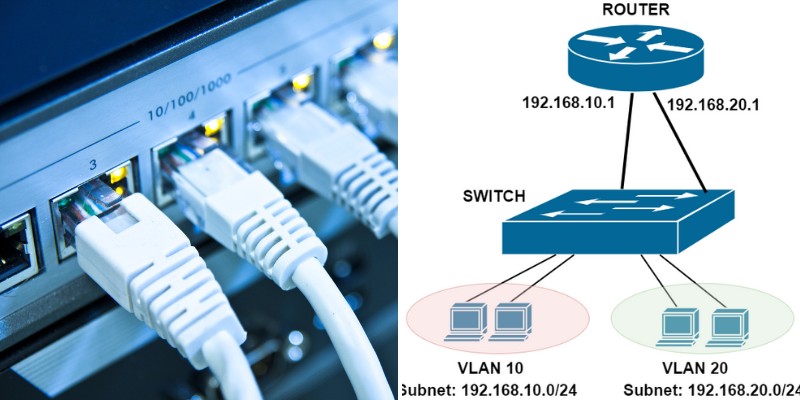
Let’s compare and discuss in more details the differences between VLANs and Subnets below. The simple network diagram below will help in our discussion.
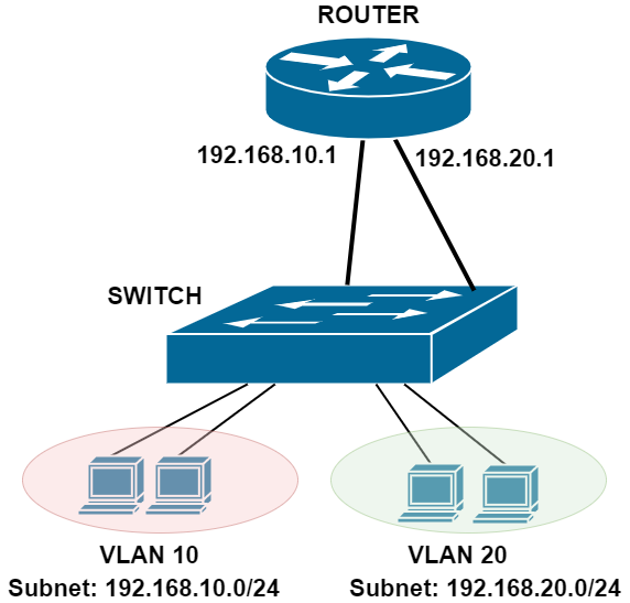
In the network above, we have two VLANs (10 and 20) and two network Subnets (192.168.10.0/24 and 192.168.20.0/24).
Although the hosts belonging in the two VLANs are connected to the same Switch, they can’t communicate between them via the switch.
If hosts in VLAN 10 want to communicate with hosts in VLAN 20, traffic from the hosts in VLAN 10 must go up to the router interface (with IP 192.168.10.1) which will route the packets to its second interface (192.168.20.1) and down to VLAN 20.
What is a VLAN
Virtual Local Area Networks or VLANs are a method of separating ethernet traffic flowing through a LAN network at Layer 2 or the Data Link layer of the OSI model.
Without VLANs every packet flowing through a network would be visible to every connected device and every device would be able to communicate with each other.
From a security perspective this is not a good thing as within a corporate environment you would not want your customer service computers for example to be able to see resources and access the finance department for example or within a College the Students computer communicating freely with the teacher computers etc.
This separation of traffic is achieved by assigning VLANs to the switch interfaces where the end devices are connected.
When traffic comes from these connected end-devices to the switch, packets are tagged with a VLAN ID number by the switch.
This is called 802.1Q Vlan tagging. When a packet reaches a switchport (access port on Cisco devices), the switch assigns an 802.1Q tag (VLAN ID) to the Ethernet frame.
Now, the switch forwards this frame only to other ports that belong in the same VLAN. If the tag matches the Vlan assigned to that interface then the packet is allowed through, if it doesn’t match then the packet is dropped.
An analogy that is often used is to imagine lanes on a highway, these separate lanes represent the different Vlans.
Another way of looking at it is to imagine there’s a building with 4 doors leading to 4 different rooms. One red, one green, one yellow and one blue.
From a group of 40 people 10 are given passes that open the red door, 10 passes for the green door, 10 passes for the yellow door and 10 passes for the blue door.
Now you can see that if someone who has a red pass tries to enter the blue door the pass won’t work so they are unable to talk to the people on the other side of the blue door, but they can go through the red door and talk to all the people who also have a red pass and have access to this room.
This is the same principle as Vlan tagging. So, what happens if a Vlan tagged interface receives a packet that does not have a Vlan tag?
By default, this packet would be dropped so this is where we would use a Native Vlan. The Native Vlan is associated with all untagged packets and by default on a Cisco switch the Native Vlan is Vlan 1.
As a security best practice this is often changed to another number. On a trunk interface, all Vlan tagged traffic can be allowed across the link or only certain Vlans can be allowed across. All untagged traffic would be tagged with the native Vlan and allowed across the trunk.
It is important that the Native Vlan matches on both sides of the trunk link because if the Native Vlan is different the switch will drop this untagged traffic at the far end of the trunk as it will see a mismatch.
What is a Subnet
A subnet is a Layer 3 IP network range that is derived after breaking down a large network range into smaller pieces through the subnetting of its IP address range.
A single class A IP address (with subnet mask 255.0.0.0) would allow 127 networks with 16,777,216 IP host addresses per network.
This would result in a lot of wasted IP addresses even for the largest networks. This is where subnetting can help.
The original class A IP address can be split into smaller chunks and these smaller chunks of IP addresses can be used to make many smaller networks using the same big address range.
To make these smaller networks the subnet mask is changed from a /8 or 255.0.0.0 to another mask that gives a smaller number of usable IP addresses.
An IP address of 10.0.0.1 with a mask of 255.255.255.0 or /24 would allow around 2-million subnetworks or subnets but only 254 usable IP addresses per subnet.
This means that by segmenting down a big IP range into smaller subnets, you have better management and more efficient use of IP address space.
In real world switched networks, each Subnet is associated with its own VLAN (as shown on out network diagram above). So, the two terms we examine here (VLAN and subnet) have a direct mapping between them.
Network administrators separate their LAN networks into several VLANs with each one having its own Layer 3 subnet.
A Layer 3 subnet is the analogy of one department room. People in the same room can communicate freely. However, if you want to go to another room (subnet) you must pass through a door (router gateway) which takes you to the other department.
Comparison of Vlans and Subnets
Subnets are used to further separate the network traffic, but the main difference between VLANs and Subnets is that VLANs are a Layer 2 method of separating ethernet traffic (this is done within the switching infrastructure) and Subnets are a Layer 3 method of separating traffic and this is carried out within the routing infrastructure.
VLANs and Subnets are used together in infrastructure security to form a defence in depth as both methods separate the traffic within the network.
VLANs, although providing separation of traffic, can communicate between them only through Layer 3 routing.
There are times when you may want different Vlans to be able to communicate. For example, if you have a File Server that is attached to a switch and configured to be in Vlan 10 and a PC that is attached to the same switch but configured in Vlan 20, then they will be unable to communicate at layer 2 because the Vlans are different.
To allow the PC to talk to the Server, a Layer 3 router must perform the “Inter-VLAN” routing. This is depicted in the basic diagram shown at the beginning of this article. Another way to provide “Inter-VLAN” routing is by using SVI on a Layer 3 switch.
Switch Virtual Interface (SVI) needs to be created on a layer 3 switch for each VLAN. Basically, the SVI is a virtual network interface which acts as the default gateway for all hosts in that VLAN.
This would mean that any devices in Vlan 10 would now be able to communicate with devices in Vlan 20 and vice versa. Below is the Cisco configuration to create the two SVI’s:
Enable
Configure terminal
Vlan 10
Name Servers
Vlan 20
Name User_PC
interface Vlan10
Description Servers
ip address 10.0.1.1 255.255.255.0
interface Vlan20
Description User PC’s
ip address 10.0.2.2 255.255.255.0
Once an SVI has been created all devices in Vlan 10 and Vlan 20 will be able to communicate with each other.
If you only want certain devices on Vlan 10 to communicate to the devices on Vlan 20 then an Access Control List (ACL) will need to be placed on the SVI to permit or deny access where required.
VLAN vs Subnet – Comparison Table
| Characteristic | VLAN | Subnet |
| OSI Layer | Layer 2 | Layer 3 |
| Traffic Isolation | At Switch Level (Ethernet) | At Router Level (IP packets) |
| Network Device Used | Configured on Network Layer 2 Switches | Configured on Network Routers or Layer 3 Switches |
| Advantages | Creates separate broadcast domains – Limits broadcasts in the network.
Provides network isolation at the lowest level. |
More efficient use of IP network space.
Having different subnets allows traffic control using firewalls or router Access Control Lists. |
| Networking Protocols | 802.1Q, MAC address | IPv4/IPv6 |
Can 2 VLANs have the same subnet?
Some people ask the question if we can have two different VLANs (e.g VLAN 10 and 20) on a switch and assign the same subnet to each VLAN (e.g 192.168.1.0/24).
The above scenario, although technically can be done, it is not recommended and does not serve any purpose.
Hosts connected to the two VLANs will not be able to communicate although they will belong in the same subnet range.
The two VLANs create two separate broadcast domains and therefore Layer 2 traffic in each VLAN will stay inside the VLAN and will not be able to reach the other VLAN. Thus, hosts will not be able to communicate between the two broadcast domains.
The proper network setup is to have different Layer 3 subnets belonging to different Layer 2 VLANs and then have a Layer 3 routing engine in order to allow communication between the two VLANs/subnets.
VLAN and Subnet Security
Let’s discuss briefly the security aspects of VLANs and subnets.
They are both used in modern networks to separate and control traffic between hosts and segregating LAN networks. They are both very useful and essential in network security.
VLAN isolation is stronger than subnet isolation in terms of security. If you separate hosts into different VLANs, then you make sure that hosts in these VLANs can not communicate between them.
For example, computers belonging to the Finance Department are assigned in VLAN 10 and Computers belonging to Engineering Department are assigned in VLAN 20. This scenario completely isolates the computers of the two Departments and you make sure they will not be able to communicate unless the traffic passes first from a Layer 3 device.
Now, subnetting also creates security isolation if you use a Layer 3/4 Firewall device to control the routing between the Layer 3 subnets. This is also a common and useful practice in network security.
Traffic from different subnets can be controlled by a Firewall in order to block or allow only the necessary packets between the subnets (in Layer 3, Layer 4 level). If the traffic between subnets passes only through a regular router, then you don’t have the same security control like a firewall.
The absolute best security practice is to have isolation at both VLAN and Subnet levels. Assign each subnet to its own physical VLAN and have a network firewall control the traffic between VLANs/subnets.
Related Posts
- Difference Between Routers and Switches in TCP/IP Networks
- 11 Different Types of IP Addresses Used in Computer Networks
- Compare and Contrast Network Topologies (Star, Mesh, Bus, Hybrid etc)
- 11 Networking Companies Like Cisco (Competitors)
- What is a Wildcard Mask – All About Wildcard Masks Used in Networking