Imagine the following situation: You are a network engineer and your boss or a customer wants you to build a cheap and easy solution to host a publicly accessible server (such as Webserver, Email server, VPN server etc) using only a regular Cisco router.
In most network designs, you will see that the usual and “proper” way to protect publicly accessible servers is to place them behind a network firewall such as Cisco ASA, Fortigate, Checkpoint, Palo Alto etc.
In this article however we will discuss and explain how to achieve the above requirement using port forwarding with a Cisco router.
This option is good in low-budget networks, in remote offices, or in SMB networks that don’t have high requirements in terms of security etc.
Port Forwarding is a feature that can be used to provide access from the Internet to internal servers in a Local Network.
Port Forwarding is based on static NAT whereby the public IP address assigned to the outside WAN interface of the router is translated to an internal private IP address and port assigned to an internal server.
Let’s see the following basic network diagram to understand our scenario better. The following is also the most common topology found in real-world networks.
Network Scenario 1
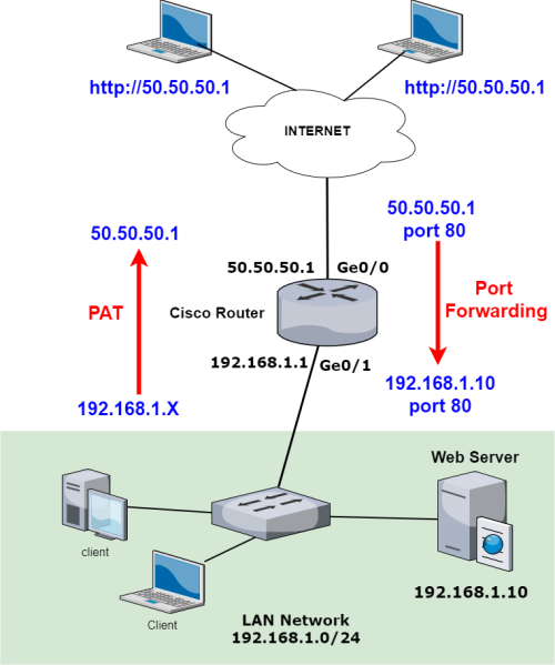
As shown from the network above, we have a LAN Network (192.168.1.0/24) with several users’ computers and also a Web Server.
I know that the above is not a good practice in terms of security because you should avoid placing a publicly-accessible server inside your internal LAN network. However, for the sake of explaining port forwarding, let’s assume we have the above setup.
We want to allow access from the Internet towards the Web Server (192.168.1.10) at port 80.
I know again that this is not a good practice because regular HTTP at port 80 is not encrypted and you should always use HTTPs at port 443.
For the sake of simplicity though let’s assume we have a Web Server listening at port 80.
Another requirement is to configure PAT (NAT overload or Port Address Translation) for allowing Outgoing traffic from the LAN network towards the Internet.
So, the router will have two different NAT types:
- NAT Overload (PAT) for translating all source IPs (192.168.1.x) for Outgoing traffic using the public WAN IP (50.50.50.1) assigned to Interface Ge0/0 of the router.
- Port Forwarding which will translate the destination IP and port 80 of Incoming traffic from the Internet into the private IP and port 80 of the Web Server. This means that incoming traffic hitting 50.50.50.1 at port 80 will be translated to destination IP 192.168.1.10 at port 80 (which is the Web Server address).
Let’s see how to configure the above.
Port Forwarding Configuration 1
R1#conf t
Enter configuration commands, one per line. End with CNTL/Z.
R1(config)#interface gigabitEthernet 0/0
R1(config-if)#ip address 50.50.50.1 255.255.255.0
R1(config-if)#ip nat outside <– Configure the WAN as NAT outside interface
R1(config-if)#no shutdown
R1(config-if)#exit
R1(config)#
R1(config)#interface gigabitEthernet 0/1
R1(config-if)#ip address 192.168.1.1 255.255.255.0
R1(config-if)#ip nat inside <– Configure the LAN as NAT inside interface
R1(config-if)#no shutdown
R1(config-if)#exit
R1(config)#
R1(config)#ip route 0.0.0.0 0.0.0.0 50.50.50.2 <– Configure default route
R1(config)#access-list 1 permit 192.168.1.0 0.0.0.255 <– Configure ACL to be used for PAT
R1(config)#ip nat inside source list 1 interface GigabitEthernet0/0 overload <– Configure PAT (NAT overload)
R1(config)#ip nat inside source static tcp 192.168.1.10 80 50.50.50.1 80 <– Configure Port Forwarding
R1(config)#end
R1#wr
NOTE:
The command which configures port forwarding has the following format:
ip nat inside source static { tcp | udp } local-ip local-port global-ip global-port [extendable]
So, from the configuration example above, the global-ip (WAN IP) 50.50.50.1 and port 80 will be translated to local-ip 192.168.1.10 port 80.
Verification
Let’s verify the port forwarding by observing the nat translations table:
R1#show ip nat translations
Pro Inside global Inside local Outside local Outside global
tcp 50.50.50.1:80 192.168.1.10:80 — —
tcp 50.50.50.1:80 192.168.1.10:80 60.60.60.2:1026 60.60.60.2:1026
The NAT table above shows that the Global IP 50.50.50.1 port 80 is mapped (translated) to Inside local 192.168.1.10:80.
Also, the table above shows that an Internet host (60.60.60.2) shown as Outside global has already accessed the Web server and created a NAT entry in the table.
Network Scenario 2
Let’s now see a slightly different topology with using port forwarding:
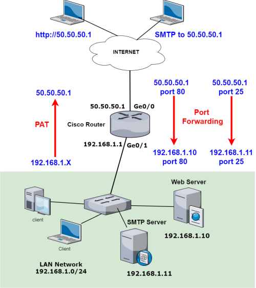
In the network above, we have two internal servers that we need to access from the Internet. The original Web Server (192.168.1.10) we have seen in the previous example and a new SMTP Server (192.168.1.11).
We will configure port forwarding on the Cisco router so that traffic hitting the public IP 50.50.50.1 at port 80 will be forwarded to the Web server and traffic hitting the WAN IP at port 25 (for SMTP) will be forwarded to the SMTP server.
Port Forwarding Configuration 2
The initial configuration of IP addresses, PAT, etc is the same as the previous example. Let’s only see how to configure Port Forwarding for the two internal servers.
R1(config)#ip nat inside source static tcp 192.168.1.10 80 50.50.50.1 80 <– Port Forwarding for Web Server
R1(config)#ip nat inside source static tcp 192.168.1.11 25 50.50.50.1 25 <– Port Forwarding for SMTP Server
Verification
Let’s verify again the port forwarding by observing the nat translations table:
R1#show ip nat translations
Pro Inside global Inside local Outside local Outside global
tcp 50.50.50.1:25 192.168.1.11:25 — —
tcp 50.50.50.1:25 192.168.1.11:25 65.12.60.10:1028 65.12.60.10:1028
tcp 50.50.50.1:80 192.168.1.10:80 — —
tcp 50.50.50.1:80 192.168.1.10:80 60.60.60.2:1026 60.60.60.2:1026
As shown from the output above, we have NAT entries for 50.50.50.1 port 25 translated to 192.168.1.11 port 25.
Also, address 50.50.50.1 port 80 is translated to 192.168.1.10 port 80.
Other Configuration Options
Another configuration option with port forwarding is to have a different external port forwarded to a different internal port on the server.
R1(config)#ip nat inside source static tcp 192.168.1.10 80 50.50.50.1 8080
The above shows that traffic hitting the public IP 50.50.50.1 at port 8080 will be translated to the private IP 192.168.1.10 at port 80.
Another option would be to have two different public ports forwarded to two different ports on the same internal server:
R1(config)#ip nat inside source static tcp 192.168.1.10 80 50.50.50.1 80
R1(config)#ip nat inside source static tcp 192.168.1.10 22 50.50.50.1 22
The option above is useful when the same internal server (192.168.1.10) runs two different services, e.g a Web server (port 80) and an SSH server (port 22).
Clearing the NAT Translations Table
If you want to clear the NAT translations table, then use the following:
R1#clear ip nat translation *
Security Considerations
Use Network Firewall Instead of Router
As we mentioned in this article, there are several security issues which need to be considered. First, it is strongly suggested to use an actual network firewall in front of publicly exposed servers (such as a Web Server, SMTP server etc).
A network firewall uses stateful inspection of traffic compared to no-inspection at all from a normal router. Moreover, the network firewall will implement also security traffic rules which will allow only the required traffic to pass (e.g port 80, 443, 25 and nothing else).
A normal router (as our examples above) allow all traffic to pass which imposes security risks. We can implement Access Control List on the router to allow only required traffic. See example config below:
ip access-list extended ALLOW_TRUSTED
permit tcp host 60.60.60.1 any eq 25
deny ip any any
Then apply this ACL to the WAN interface at the inbound direction.
Use Non-Standard External Ports for Sensitive Services
For services like SSH, RDP, or database access, avoid using default ports in port forwarding. Use an uncommon external port to reduce exposure to automated scans and attacks.
For example, hackers know that all Linux servers on the internet listen by default to port 22 for allowing SSH access to the server over the internet.
Therefore, they develop automated scanning tools to find open ports 22 on a range of public IP addresses in order to start using login attempts (such as “brute-force”, “password spraying” etc) to gain access to the server.
A good security practice is to use a non-standard external port (e.g port 2222 for SSH instead of 22) so that automated scanning tools will not look for this port.
Example:
ip nat inside source static tcp 192.168.1.10 22 50.50.50.1 2222
Then we should tell our external users to connect to port 2222 which will be port-forwarded to internal port 22 on our internal server.