The depletion of the public IPv4 address space has forced the internet community to think about alternative ways of addressing networked hosts.
Network Address Translation (NAT) therefore was introduced to overcome these addressing problems that occurred with the rapid expansion of the Internet.
Even if NAT was suggested as a temporary solution, it has been adopted by all network hardware manufacturers, and it is considered a very useful technology, not only for IP address conservation, but also for many other purposes including security.
Basically NAT allows a single network device (e.g a router, firewall etc) to act as an agent between a private local area network and a public network such as the Internet.
The purpose of this NAT device is to translate the source IP addresses of the internal network hosts into public routable IP addresses in order to communicate with the Internet.
Some of the advantages of using NAT in IP networks are the following:
- NAT helps to mitigate the depletion of the global public IP address space
- Networks can now use the RFC 1918 private address space internally and still have a way to access the Internet using NAT.
- NAT increases security by hiding the internal network topology and addressing scheme.
Cisco IOS routers support different types of NAT as will be explained below. NAT has many forms and can work in several ways, but in this post I will explain the most important types of NAT.
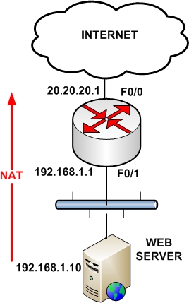
For the next 2 scenarios we will be using the following simple network:
1. Overloading or Port Address Translation (PAT)
This is the most frequently used form of NAT in IP networks. It uses the concept of “many-to-one” translation where multiple connections from different internal hosts are “multiplexed” into a single registered (public) IP address using different source port numbers.
This type of NAT allows a maximum of 65,536 internal connections to be translated into a single public IP. This type of NAT is very useful in situations where our ISP has assigned us only a single public IP address, as shown on the diagram below.
All IP addresses of the LAN network (192.168.1.0/24) will be translated using the public IP of the router (20.20.20.1).
interface FastEthernet0/0
ip address 20.20.20.1 255.255.255.0
ip nat outside
!
interface FastEthernet0/1
ip address 192.168.1.1 255.255.255.0
ip nat inside
!
access-list 1 permit 192.168.1.0 0.0.0.255
ip nat inside source list 1 interface FastEthernet0/0 overload
2. Static Port Address Translation (Port Redirection)
Assume now that we have only one public IP address which is the one configured on the outside interface of our border router. We want traffic hitting our router’s public IP 20.20.20.1 on port 80 to be redirected to our internal Web Server at IP 192.168.1.10
interface FastEthernet0/0
ip address 20.20.20.1 255.255.255.0
ip nat outside
!
interface FastEthernet0/1
ip address 192.168.1.1 255.255.255.0
ip nat inside
!
ip nat inside source static tcp 192.168.1.10 80 20.20.20.1 80
3. Configuring Static NAT
NAT can be performed both statically and dynamically. Static NAT simply maps one private IP address to a single public IP address, and this is the flavor of NAT we are discussing in this section.
A Cisco router performing NAT divides its universe into the inside and the outside. Typically the inside is a private enterprise, and the outside is the public Internet. In addition to the notion of inside and outside, a Cisco NAT router classifies addresses as either local or global.
A local address is an address that is seen by devices on the inside, and a global address is an address that is seen by devices on the outside. Given these four terms, an address may be one of four types:
- Inside local addresses are assigned to inside devices. These addresses are not advertised to the outside.
- Inside global are addresses by which inside devices are known to the outside.
- Outside local are addresses by which outside devices are known to the inside.
- Outside global addresses are assigned to outside devices. These addresses are not advertised to the inside.
Let’s jump right into static NAT configuration on a Cisco router as shown in the Figure below:

R1 is the router performing Network Address Translation (NAT) and has two interfaces: Fa0/0 on the inside and Fa0/1 on the outside. The specific IP addresses involved are:
|
NAT Address Type |
IP Address |
|
Inside local |
192.168.1.2 |
|
Inside global |
89.203.12.47 |
|
Outside local |
202.14.35.28 |
|
Outside global |
202.14.35.28 |
Table 1 NAT Addresses for Figure Above
You probably know very well how to configure IP addresses on router interfaces, so we skip those configuration steps and move straight to the interesting stuff. First, we have to assign Fa0/0 as NAT inside interface and Fa0/1 as NAT outside interface on R1. This would tell the router that interesting traffic entering or exiting these two interfaces will be subject to address translation.
R1#conf term
Enter configuration commands, one per line. End with CNTL/Z.
R1(config)#interface Fa0/0
R1(config-if)#ip nat inside
R1(config-if)#interface Fa0/1
R1(config-if)#ip nat outside
R1(config-if)#end
Now we would tell the router how to perform address translation and mention which IP addresses (source or destination) to re-write in packets moving between the inside and outside interfaces. Here we go:
R1(config)#ip nat inside source static 192.168.1.2 89.203.12.47
Here, we are telling the router to perform NAT on packets coming into the router on the inside interface Fa0/0. More specifically the router would identify which of these packets have a source IP address of 192.168.1.2 and would change it to 89.203.12.47 before forwarding the packet out the outside interface Fa0/1. Similarly, return packets coming in at outside interface Fa0/1 would undergo translation of destination IP address.
Let’s now verify if NAT is actually working as it is supposed to work. There are a couple of very useful Cisco IOS commands that can be used to do just that. Command show ip nat statistics displays the number of static and dynamic NAT translations, inside and outside interfaces, and the number of hits and misses.
R1#show ip nat statistics
Total active translations: 1 (1 static, 0 dynamic; 0 extended)
Outside interfaces:
FastEthernet0/1
Inside interfaces:
FastEthernet0/0
Hits: 0 Misses: 0
CEF Translated packets: 0, CEF Punted packets: 0
Expired translations: 0
Dynamic mappings:
Appl doors: 0
Normal doors: 0
Queued Packets: 0
Command show ip nat translations displays the IP addresses for NAT translations.
R1#show ip nat translations
Pro Inside global Inside local Outside local Outside global
— 89.203.12.47 192.168.1.2 — —
As you see in the above output, we have one NAT entry configured with Inside global address 89.203.12.47 and Inside local address 192.168.1.2 specified. Outside local and Outside global addresses are blank because our NAT configuration does not change those addresses.
Let’s now go to the PC and ping the Server before running the command show ip nat translations again to see if it makes any difference.
R1#show ip nat statistics
Total active translations: 2 (1 static, 1 dynamic; 1 extended)
Outside interfaces:
FastEthernet0/1
Inside interfaces:
FastEthernet0/0
Hits: 10 Misses: 0
CEF Translated packets: 10, CEF Punted packets: 0
Expired translations: 0
Dynamic mappings:
Appl doors: 0
Normal doors: 0
Queued Packets: 0
R1#show ip nat translations
Pro Inside global Inside local Outside local Outside global
icmp 89.203.12.47:1 192.168.1.2:1 202.14.35.28:1 202.14.35.28:1
— 89.203.12.47 192.168.1.2 — —
As you can see in the above output, NAT is active as manifested by the appearance of an additional dynamic entry for ICMP protocol and some additional hits, corresponding to our ping attempt from PC to Server.
We just configured and verified a simple NAT scenario translating only the source or destination (not both at the same time) IP addresses of packets moving between inside and outside interfaces.
This sort of NAT configuration is called static NAT as a single inside local IP address is statically mapped to a single outside local IP address.
Another important feature of NAT is static Port Address Translation (PAT). Static PAT is designed to allow one-to-one mapping between local and global addresses.
A common use of static PAT is to allow Internet users from the public network to access a Web server located in the private network.
Let’s assume we intend to host a Web server on the inside on the same PC, that has an IP address 192.168.1.2. The following configuration line would allow us to do just that:
R1(config)#ip nat inside source static tcp 192.168.1.2 80 89.203.12.47 80
This configuration line performs the static address translation for the Web server. With this configuration line, users that try to reach 89.203.12.47 port 80 (www) are automatically redirected to 192.168.1.2 port 80 (www). In our case, 192.168.1.2 is the IP address of the PC which is also the Web server.
This configuration can be verified using the same two NAT verification commands:
show ip nat translations and show ip nat statistics.
Notice that the address 89.203.12.47 with port number 80 (HTTP) translates to 192.168.1.2 port 80, and vice versa. Therefore, Internet users can browse the Web server even though the Web server is on a private network with a private IP address.
Related Posts
- How to Configure Port Forwarding on Cisco Router (With Examples)
- Redistribution and OSFP – Discussion With Cisco Commands Examples
- Cisco HSRP States and Troubleshooting (With Commands)
- Cisco Router Login – GUI Login and How to Secure Your Access
- Route Filtering and OSPF – Workaround With Distribute List Filtering