HSRP (Hot Standby Router Protocol) is the Cisco proprietary protocol for providing redundancy in router networks. The standard router redundancy protocol which is used by other vendors is VRRP (Virtual Router Redundancy Protocol), however Cisco has created its own proprietary protocol (HSRP) which works very well on Cisco routers.
In a Local Area Network (LAN), all hosts (PC, Servers etc) have a single default gateway address configured which is used to route packets outside the LAN.
If that single default gateway fails, then communication outside the LAN is not possible. With HSRP we can have two gateway routers, one active and one standby, which will provide resiliency regarding the default gateway address.
Using HSRP, the two routers will have a physical IP address configured on their LAN-facing interface, but they will have also a Virtual (HSRP address) which will be used as the default gateway address for hosts on the LAN.
No matter which router gateway is up and running (either the primary or the secondary), the virtual HSRP address will stay the same.
In this article we will discuss two different network scenarios where HSRP can be used to provide redundancy between two paths from an internal LAN network towards the outside world (WAN or Internet).
HSRP Scenario 1
Let’s see a diagram below to explain the first network example case:

First of all, HSRP must be configured between interfaces that have Layer2 connectivity between them. From the diagram above, HSRP will be running between interfaces FE0/1 on the two LAN routers.
Interface FE0/1 on RTR-A will have a physical IP address 10.10.10.1 and interface FE0/1 on RTR-B will have a physical IP address 10.10.10.2.
An HSRP address 10.10.10.3 will be also configured on both routers. This address will serve as the default gateway address for all hosts on the LAN. RTR-A will be configured as the Active HSRP router by setting a higher hsrp priority.
With HSRP, we can also track a specific interface. This means that if the tracked interface of the active router fails, then HSRP will trigger a failover to the standby router.
Let’s see an actual configuration below:
Configuration
Router RTR-A
RTR-A(config)# int fa0/1
RTR-A(config-if)# ip address 10.10.10.1 255.255.255.0
! enable HSRP group 1 and set the virtual address to 10.10.10.3
RTR-A(config-if)# standby 1 ip 10.10.10.3
! preempt allows the router to become the active router when its priority is higher
RTR-A(config-if)# standby 1 preempt
! increase its priority to 110 to make it active (default priority is 100)
RTR-A(config-if)# standby 1 priority 110
! track the WAN interface FE0/0
RTR-A(config-if)# standby 1 track fa0/0
Router RTR-B
RTR-B(config)# int fa0/1
RTR-B(config-if)# ip address 10.10.10.2 255.255.255.0
! enable HSRP group 1 and set the virtual address to 10.10.10.3
RTR-B(config-if)# standby 1 ip 10.10.10.3
! preempt allows the router to become the active router when its priority is higher
RTR-B(config-if)# standby 1 preempt
! set priority to 100 to make it the standby router (this is the default value)
RTR-B(config-if)# standby 1 priority 100
! track the WAN interface FE0/0
RTR-B(config-if)# standby 1 track fa0/0
That’s it. Now configure a default gateway address of 10.10.10.3 for your LAN hosts.
HSRP Scenario 2
Here we have a network setup which is very useful in enterprises for providing ISP redundancy.
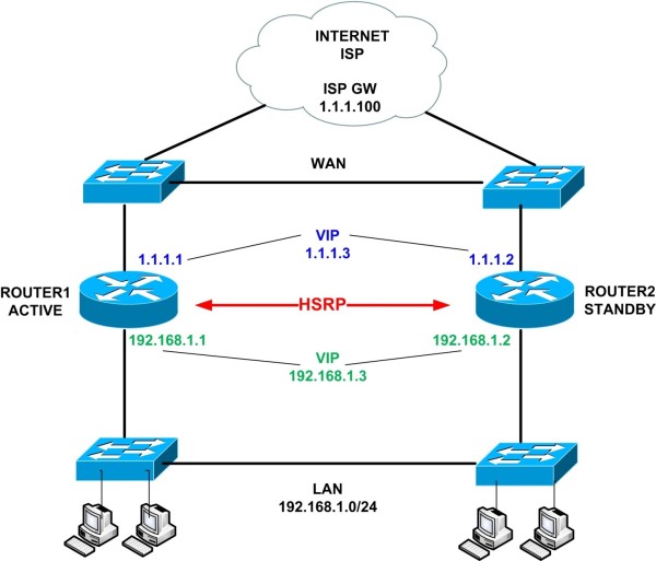
In our network above we will configure HSRP on both the LAN and the WAN interfaces of the two Routers. Remember that for HSRP to work, we need to provide Layer2 connectivity between the routers.
The two switches on the LAN side and the two switches on the WAN side will provide the required L2 connectivity for HSRP to run on both the LAN and WAN connections.
The network above can be implemented in a single building/data center, but can also be implemented in two separate buildings/data centers.
By extending the two LAN and WAN switches and connecting them with a network cable (usually fiber optic cable) you can easily extend the network in two different buildings or data centers.
Also, by configuring HSRP on the WAN side, we can have two advantages:
- Provide redundancy on the two ISP links.
- The network will provide a single IP address on the WAN side so that we can configure inbound traffic to reach internal servers (by configuring static NAT for example).
The limitation of the above though is that you can have only one ISP which must provide an Ethernet connectivity for the WAN links.
Another important aspect of the configuration that we’ll implement is “reachability tracking”. HSRP supports different types of tracking, such as interface tracking, routing table tracking, reachability tracking etc.
In our example we will configure reachability tracking using SLA. This means that if a destination IP stops responding to ICMP requests, then HSRP will trigger a failover condition and the standby router will take over and start passing traffic.
Configuration
Note: Only important commands are shown
STEP1
First configure the tracking mechanism on the active router.
The following commands will configure a Service Level Agreement (SLA) operation which will send ICMP ECHO packets to destination IP 1.1.1.100 from source interface Ethernet0/0 (which is the WAN interface of ROUTER1).
The packets will be sent continuously from the router to the destination IP in order to check reachability of the destination. This essentially checks if the WAN link is up and the whole path is up as well.
ROUTER1(config)# ip sla 1
ROUTER1(config-ip-sla)# icmp-echo 1.1.1.100 source-interface Ethernet0/0
ROUTER1(config-ip-sla)# ip sla schedule 1 life forever start-time now
Next we’ll create a tracking object and bind it to the SLA mechanism above. This tracking object number (10) will be used in the HSRP configuration later.
ROUTER1(config)# track 10 ip sla 1 reachability
STEP2
Now let’s configure IP addresses and HSRP on the routers.
ROUTER1
First let’s enable HSRP on the WAN interface with Virtual IP 1.1.1.3
ROUTER1(config)# interface ethernet 0/0
ROUTER1(config-if)# description WAN Interface
ROUTER1(config-if)# ip address 1.1.1.1 255.255.255.0
ROUTER1(config-if)# standby 1 ip 1.1.1.3 <- Create HSRP Group 1 and assign Virtual IP 1.1.1.3
ROUTER1(config-if)# standby 1 priority 101 <-Assign priority above 100 to make router primary/active
ROUTER1(config-if)# standby 1 preempt <- Makes router active if it has higher priority
ROUTER1(config-if)# standby 1 track 10 decrement 5 <- Assign tracking object 10 to HSRP group which will decrement the priority value by 5 if the tracked object is not reachable.
Now let’s enable HSRP on the LAN interface as well and create a Virtual IP 192.168.1.3
ROUTER1(config)# interface ethernet 0/1
ROUTER1(config-if)# description LAN Interface
ROUTER1(config-if)# ip address 192.168.1.1 255.255.255.0
ROUTER1(config-if)# standby 1 ip 192.168.1.3 <- Create HSRP Group 1 and assign Virtual IP 192.168.1.3
ROUTER1(config-if)# standby 1 priority 101 <- Assign priority above 100 to make router primary/active
ROUTER1(config-if)# standby 1 preempt <- Makes router active if it has higher priority
ROUTER1(config-if)# standby 1 track 10 decrement 5 <- Assign tracking object 10 to HSRP group which will decrement the priority value by 5 if the tracked object is not reachable.
NOTE:
The tracking object 10 above will decrement the priority value of the router by 5 (only if the tracked destination IP 1.1.1.100 is not reachable). This means that priority will become 101-5=96 which will be lower than the default priority of 100 which is assigned on the standby router (ROUTER2). Therefore, the standby router will become active.
ROUTER1(config)# ip route 0.0.0.0 0.0.0.0 1.1.1.100 <- Default Gateway route to ISP
ROUTER2
The configuration is similar but we don’t have to configure tracking on this router.
ROUTER2(config)# interface ethernet 0/0
ROUTER2(config-if)# description WAN Interface
ROUTER2(config-if)# ip address 1.1.1.2 255.255.255.0
ROUTER2(config-if)# no shut
ROUTER2(config-if)# standby 1 ip 1.1.1.3 <- The HSRP Group number (1) must be same as ROUTER1
ROUTER2(config-if)# standby 1 preempt
ROUTER2(config)# interface ethernet 0/1
ROUTER2(config-if)# description LAN Interface
ROUTER2(config-if)# ip address 192.168.1.2 255.255.255.0
ROUTER2(config-if)# no shut
ROUTER2(config-if)# standby 1 ip 192.168.1.3
ROUTER2(config-if)# standby 1 preempt
ROUTER2(config)# ip route 0.0.0.0 0.0.0.0 1.1.1.100 <- Default Gateway route to ISP
STEP3
Let’s now see some verification commands:
Normal Operation
ROUTER1# show standby
Ethernet0/0 – Group 1
State is Active
2 state changes, last state change 00:07:00
Virtual IP address is 1.1.1.3
Active virtual MAC address is 0000.0c07.ac01
Local virtual MAC address is 0000.0c07.ac01 (v1 default)
Hello time 3 sec, hold time 10 sec
Next hello sent in 1.184 secs
Preemption enabled
Active router is local
Standby router is 1.1.1.2, priority 100 (expires in 10.048 sec)
Priority 101 (configured 101)
Group name is “hsrp-Et0/0-1” (default)
Ethernet0/1 – Group 1
State is Active
5 state changes, last state change 00:02:32
Virtual IP address is 192.168.1.3
Active virtual MAC address is 0000.0c07.ac01
Local virtual MAC address is 0000.0c07.ac01 (v1 default)
Hello time 3 sec, hold time 10 sec
Next hello sent in 2.496 secs
Preemption enabled
Active router is local
Standby router is 192.168.1.2, priority 100 (expires in 9.728 sec)
Priority 101 (configured 101)
Track object 10 state Up decrement 5
Group name is “hsrp-Et0/1-1” (default)
ROUTER1#show track
Track 10
IP SLA 1 reachability
Reachability is Up
Latest operation return code: OK
Latest RTT (millisecs) 1
Tracked by:
HSRP Ethernet0/0 1
HSRP Ethernet0/1 1
Failover Case
ROUTER1#show standby
Ethernet0/0 – Group 1
State is Standby
4 state changes, last state change 00:01:39
Virtual IP address is 1.1.1.3
Active virtual MAC address is 0000.0c07.ac01
Local virtual MAC address is 0000.0c07.ac01 (v1 default)
Hello time 3 sec, hold time 10 sec
Next hello sent in 1.104 secs
Preemption enabled
Active router is 1.1.1.2, priority 100 (expires in 10.848 sec)
Standby router is local
Priority 96 (configured 101)
Track object 10 state Down decrement 5
Group name is “hsrp-Et0/0-1” (default)
Ethernet0/1 – Group 1
State is Standby
7 state changes, last state change 00:06:08
Virtual IP address is 192.168.1.3
Active virtual MAC address is 0000.0c07.ac01
Local virtual MAC address is 0000.0c07.ac01 (v1 default)
Hello time 3 sec, hold time 10 sec
Next hello sent in 0.208 secs
Preemption enabled
Active router is 192.168.1.2, priority 100 (expires in 8.176 sec)
Standby router is local
Priority 96 (configured 101)
Track object 10 state Down decrement 5
Group name is “hsrp-Et0/1-1” (default)
ROUTER1#show track
Track 10
IP SLA 1 reachability
Reachability is Down
Latest operation return code: Timeout
Tracked by:
HSRP Ethernet0/0 1
HSRP Ethernet0/1 1
NOTE: As shown above, when reachability is down (i.e destination IP does not respond to ICMP requests), the priority of active router is reduced to 96 and therefore the standby router (ROUTER2) – which has priority 100 – will become active.
Related Posts
- How to Configure Port Forwarding on Cisco Router (With Examples)
- Redistribution and OSFP – Discussion With Cisco Commands Examples
- Cisco HSRP States and Troubleshooting (With Commands)
- Cisco Router Login – GUI Login and How to Secure Your Access
- Route Filtering and OSPF – Workaround With Distribute List Filtering