Policy Based Routing (PBR) is a feature that has been supported on Cisco Routers for ages. However, Cisco ASA firewalls didn’t support this until version 9.4.1 and later. Finally Cisco acknowledged the usefulness of PBR on firewall devices and has implemented this on ASA as well.
In this article I will show you how to configure two important scenarios of Policy Based Routing on ASA. Before moving forward let’s discuss first some essential concepts about the topic.
Explanation of Policy Based Routing
But what is PBR? The short answer is that PBR allows routing to be performed based on criteria other than destination IP address.
The traditional form of routing (which is used by default on any routing device) is based on the destination IP address of the packet.
This means that the routing devices (router, Layer3 switch, firewall etc) will look at the destination IP address in the header of a packet and forward (route) the packet to the proper outgoing interface of the device based on the routing table in order to reach the desired destination.
With PBR, the network device can make routing decisions based on various other criteria such as source IP address, source port, protocol, destination port etc and also combination of these.
This means for example that a routing device can receive a packet and look at its source IP address (instead of destination) and route the packet according to its PBR policy.
Some popular use-cases for PBR on ASA
Cisco ASA firewalls are usually used as border network devices connecting the Enterprise network with the ISP and hence the Internet. Many Enterprises utilize two ISP connections for redundancy and for bandwidth efficiency reasons.
One popular scenario therefore is to route some traffic to ISP1 and some other traffic to ISP2. For example, you can route all Web traffic (HTTP, HTTPs) through ISP1 and all other traffic through ISP2.
Another example could be to route traffic originating from the Engineering department via ISP1 and traffic originating from the Accounting department to go through ISP2.
There are numerous cases that PBR can be used. In this article we will describe two popular scenarios and its up to you to take if from there once you learn how it works on ASA.
Lets now see the actual configuration of PBR for our two scenarios on ASA firewalls.
1) Policy Based Routing According to the Destination Protocol
In this use-case, our ASA firewall is connected to two ISPs as shown on the diagram below:
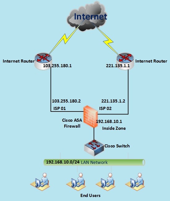
The requirement is to route Web traffic (HTTP port 80 and HTTPs port 443) via ISP01 and all the other Internet traffic via ISP02.
Configuration
Step 1
First configure the interfaces:
interface GigabitEthernet0/0
nameif inside
security-level 100
ip address 192.168.10.1 255.255.255.0
interface GigabitEthernet0/1
nameif ISP01
security-level 0
ip address 103.255.180.2 255.255.255.252
interface GigabitEthernet0/2
nameif ISP02
security-level 0
ip address 221.135.1.2 255.255.255.252
Step 2
Create an Access Control List (ACL) which will match the traffic that we want to be handled by our PBR policy.
object-group services WEB-ports tcp <– create an object group for ports 80,443
port-object eq 443
port-object eq 80
access-list PBR_ACL extended permit tcp 192.168.10.0 255.255.255.0 any object-group WEB-ports
The ACL above matches traffic from the inside network (192.168.10.0/24) having destination ports of 80 and 443.
Step 3
Just like PBR on IOS routers, we need to create a route-map which will match the traffic in ACL created above and then apply a routing policy to this traffic flow.
In our case we’ll apply a next-hop IP to this traffic flow so that packets will be routed via ISP01 (103.255.180.1).
route-map PBR permit 2 <– create the route-map and give it a name “PBR”
match ip address PBR_ACL <– match the traffic identified in ACL created above
set ip next-hop 103.255.180.1 <– set the next hop of the traffic to be ISP01
Step 4
Apply the PBR policy to the “Ingress” interface that we want to enforce this routing policy. This interface is the “inside” interface (Gig0/0) of our internal network.
interface GigabitEthernet0/0
nameif inside
security-level 100
ip address 192.168.10.1 255.255.255.0
policy-route route-map PBR <– apply the PBR policy to this interface
Step 5
We are not done yet. We need to take care of NAT and also configure proper default routes as well.
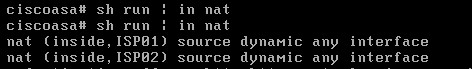
nat (inside,ISP01) 1 source dynamic any interface
nat (inside,ISP02) 2 source dynamic any interface
The above NAT rules create dynamic NAT rules (Port Address Translation-PAT) using the corresponding outgoing interface of the ASA for traffic going from “inside” to “ISP01” and also for “inside” to “ISP02”.
route ISP01 0.0.0.0 0.0.0.0 103.255.180.1 50 <– create default route with Administrative Distance 50
route ISP02 0.0.0.0 0.0.0.0 221.135.1.1 <– create default route with the default AD of 1
The above default routes will send normal traffic via ISP02 (has lower AD number of 1 compared to 50 of the first default route). However, traffic matching our PBR policy (ports 80, 443) will flow through ISP01.
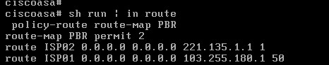
Verification Commands
Lets now see some verification commands for the configuration we have just finished:
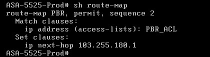
The command above “show route-map” shows a summary of our route-map (what ACL we are matching and what is the policy for this traffic “next-hop IP”).
Simulate HTTPs connection
![]()
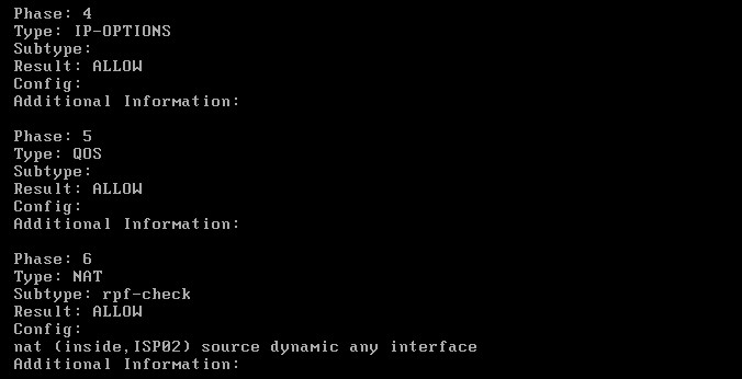
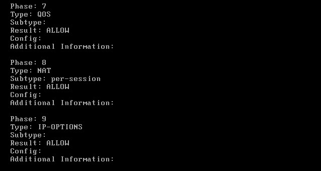
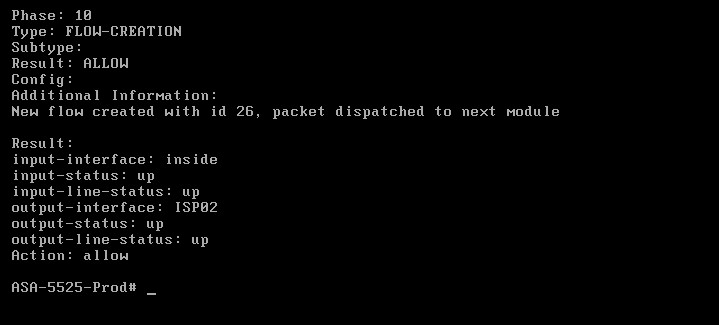
The packet-tracer above will simulate an HTTPs connection going via ISP01. The result is shown below:
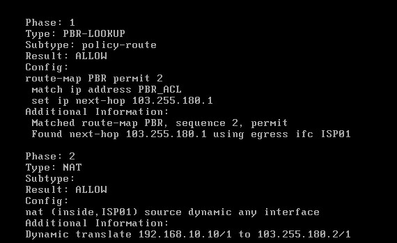
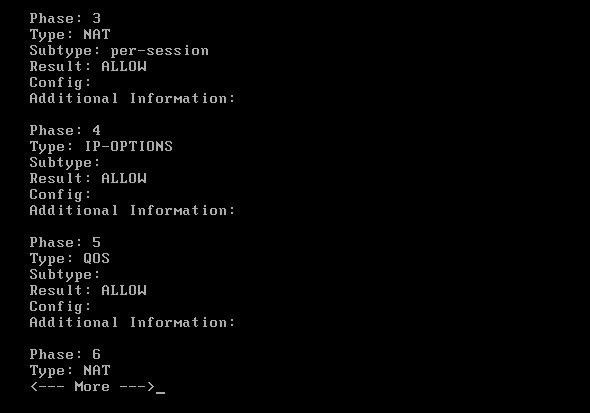
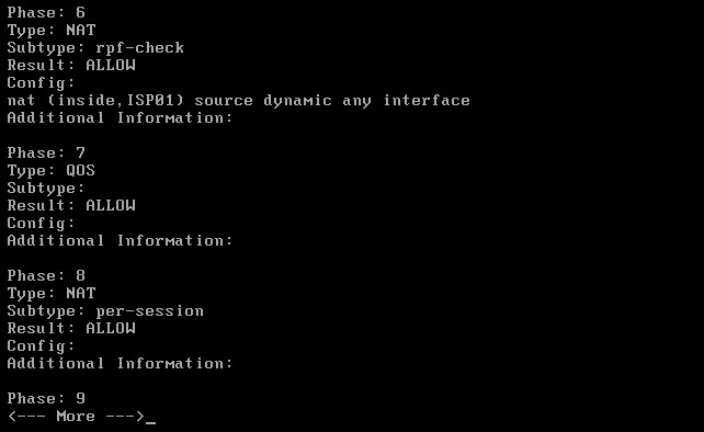
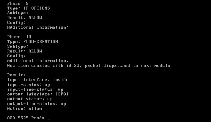
As you can see from the packet-tracer output above, HTTPs (port 443) traffic is matched by Policy Based Routing thus packets go out from 103.255.180.1 (ISP01) after the dynamic NAT translation.
Simulate SSH Connection
Now let’s see how other traffic is handled. We will simulate an SSH connection (port 22) and see how will be routed:
![]()
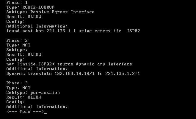
As shown from the packet tracer output above, SSH traffic (with destination port 22) is handled by the normal “ROUTE-LOOKUP” mechanism of the firewall and therefore is routed out from the default next-hop address 221.135.1.1 (ISP02).
NAT Details
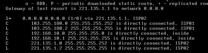
Route Details
Routing Table
2) Policy Based Routing According to Source Networks
In this use-case, our ASA firewall is connected again to two ISPs as shown on the diagram below:
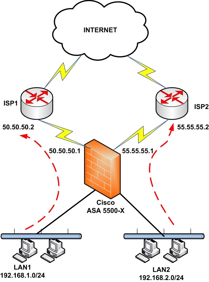
However, Policy Based Routing will be configured to handle the source networks LAN1 and LAN2. The requirement is to route LAN1 via ISP1 and LAN2 via ISP2.
Configuration
Step 1
First configure the interfaces:
interface GigabitEthernet0/0
nameif LAN1
security-level 100
ip address 192.168.1.1 255.255.255.0
interface GigabitEthernet0/1
nameif LAN2
security-level 100
ip address 192.168.2.1 255.255.255.0
interface GigabitEthernet0/2
nameif ISP1
security-level 0
ip address 50.50.50.1 255.255.255.252
interface GigabitEthernet0/3
nameif ISP2
security-level 0
ip address 55.55.55.1 255.255.255.252
Step 2
Create an Access Control List (ACL) which will match the traffic that we want to be handled by our PBR policy.
access-list PBR_ACL1 extended permit ip 192.168.1.0 255.255.255.0 any <– matches LAN1
access-list PBR_ACL2 extended permit ip 192.168.2.0 255.255.255.0 any <– matches LAN2
The two ACLs above match traffic from LAN1 and LAN2 going out to any destination.
Step 3
Like the first scenario, here we’ll configure the route-map which will match the traffic in ACLs created above and then apply a routing policy to the traffic flows.
route-map PBR permit 2 <– create the route-map and give it a name “PBR”
match ip address PBR_ACL1 <– match the traffic of LAN1 identified in ACL1 created above
set ip next-hop 50.50.50.2 <– set the next hop of LAN1 traffic to be ISP1
route-map PBR permit 3 <– create another entry in the same route-map
match ip address PBR_ACL2 <– match the traffic of LAN2 identified in ACL2 created above
set ip next-hop 55.55.55.2 <– set the next hop of LAN2 traffic to be ISP2
Step 4
Apply the PBR policy to the “Ingress” interfaces that we want to enforce this routing policy. In our case we will apply the same policy to both internal networks (LAN1, LAN2).
interface GigabitEthernet0/0
nameif LAN1
security-level 100
ip address 192.168.1.1 255.255.255.0
policy-route route-map PBR <– apply the PBR policy to this interface
interface GigabitEthernet0/1
nameif LAN2
security-level 100
ip address 192.168.2.1 255.255.255.0
policy-route route-map PBR <– apply the same PBR policy to this interface
Step 5
Again, we need to take care of NAT since we must translate the private internal IP networks to public IP address in order to access the Internet.
nat (LAN1,ISP1) 1 source dynamic any interface
nat (LAN2,ISP2) 2 source dynamic any interface
Note that we haven’t configured any default routes here. You can configure one default route if you want towards your primary ISP as shown below (optional).
route ISP1 0.0.0.0 0.0.0.0 50.50.50.2
Also, you can run several verification and packet-tracer commands similar to scenario1 to debug or troubleshoot any possible problems.
Summary
In this article we have configured two popular practical use-cases of Policy Based Routing on Cisco ASA firewalls. The first scenario focused on PBR based on destination protocol and the second scenario described a use-case of PBR based on source IP addresses.
Related Posts
- Prevent Spoofing Attacks on Cisco ASA using RPF
- Configuring Connection Limits on Cisco ASA Firewalls – Protect from DoS
- Configuring AAA Authentication-Authorization-Accounting on Cisco ASA Firewall (TACACS+, RADIUS)
- Cisco ASA Firewall Management Interface Configuration (with Example)
- How to Configure Access Control Lists on a Cisco ASA 5500/5500-X Firewall (with Examples)