Basic Cisco 800 Router Configuration for Internet Access

The Cisco 800 series routers are part of the “Branch Office” category, used mainly for SOHO purposes or for connecting remote branch offices to a central location. They are “fixed hardware configuration” devices, meaning that they don’t have any plug-in hardware slots for inserting additional interfaces to the device (all the interfaces are fixed).

All the 800 series models come with a 4-port 10/100 managed switch used for connecting the internal LAN computers, and with an IOS software that supports security features including the Firewall set. The main difference of each model is the WAN interface. All models that end with “1” in the model number (i.e 851, 861, 871, 881, 891) have a 10/100 Fast Ethernet interface as a WAN port. The other models have an xDSL type WAN port (i.e ADSL, G.SHDL, VDSL2). Also, all models have the option of a WiFi Radio interface (the model number ends with a “W”, e.g 851W, 857W, 861W etc).

In this post I will describe a basic configuration scenario for connecting a Cisco 800 router for Internet access. I will use a model with an Ethernet WAN interface (such as 851, 861, 871, etc) since those models are the most popular.

Something to have in mind for all 800 series routers, the four LAN interfaces (FE0 up to FE3) are Layer2 switch interfaces that are assigned by default to Vlan1. This means that you can not assign an IP address directly to the LAN interfaces. The IP address for the LAN-facing side of the router is assigned under “interface Vlan1”. On the other hand, the WAN interface (FE4) is a normal Layer3 router port, which means you can assign an IP address directly on the interface (“interface FastEthernet4”).

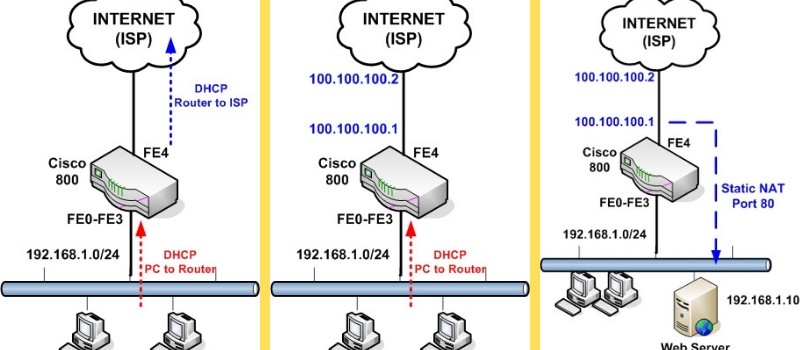
I will describe three basic scenarios which are frequently encountered in real networks.

  1. Scenario 1: WAN IP address of router is assigned dynamically by the ISP. LAN IP addresses assigned dynamically from the router to the internal PCs.
  2. Scenario 2: WAN IP address of router is static. LAN IP addresses assigned dynamically from the router.
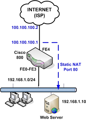
  3. Scenario 3: WAN IP address of router is static. An internal LAN Web Server exists. The router performs a static Port NAT (port redirection) to forward traffic from Internet towards the internal Web Server.

Scenario 1:

Configuration:

The following is the basic configuration needed for the simple scenario above.

configure terminal

enable secret somesecretpassword

! Configure the DHCP pool to assign addresses to internal hosts
ip dhcp pool vlan1pool
network 192.168.1.0 255.255.255.0
default-router 192.168.1.1
dns-server 100.100.100.36

! Do not assign addresses 1 to 30
ip dhcp excluded-address 192.168.1.1 192.168.1.30

! This is the LAN facing interface of the 800 router. Used as gateway for PCs
interface vlan 1
ip address 192.168.1.1 255.255.255.0
ip nat inside
no shut

! Interfaces FE0 to FE3 are Layer 2 interfaces
interface FastEthernet0
no shut
interface FastEthernet1
no shut

interface FastEthernet2
no shut

interface FastEthernet3
no shut

! This is the WAN interface getting address via DHCP from the ISP
interface FastEthernet 4
no shut
ip address dhcp
ip nat outside

! Configure NAT. All internal hosts will be nated on the WAN interface
ip nat inside source list 1 interface fastethernet4 overload
access-list 1 permit 192.168.1.0 0.0.0.255

ip route 0.0.0.0 0.0.0.0 fastethernet4

line vty 0 4
password somestrongpassword

Scenario 2:

Configuration:

This is the same configuration as scenario 1 except that the WAN IP address is static and also the default gateway of our ISP is known.

The only difference from the configuration above is on the WAN interface and on default route:

! This is the WAN interface with static IP

interface FastEthernet 4
no shut
ip address 100.100.100.1 255.255.255.0
ip nat outside

ip route 0.0.0.0 0.0.0.0 100.100.100.2

Scenario 3:

Configuration:

Here the WAN address is static and we have also an internal Web Server for which we need to allow HTTP access from Internet. To do this we must configure a static NAT with port redirection. Traffic that comes towards our WAN public address 100.100.100.1 on port 80 will be redirected by the router to the internal Web Server at address 192.168.1.10 on port 80.

configure terminal

enable secret somesecretpassword

! Configure the DHCP pool to assign addresses to internal hosts
ip dhcp pool vlan1pool
network 192.168.1.0 255.255.255.0
default-router 192.168.1.1
dns-server 100.100.100.36

! Do not assign addresses 1 to 30
ip dhcp excluded-address 192.168.1.1 192.168.1.30

! This is the LAN facing interface of the 800 router. Used as gateway for PCs
interface vlan 1
ip address 192.168.1.1 255.255.255.0
ip nat inside
no shut

! Interfaces FE0 to FE3 are Layer 2 interfaces
interface FastEthernet0
no shut

interface FastEthernet1
no shut

interface FastEthernet2
no shut

interface FastEthernet3
no shut

! This is the WAN interface with static IP
interface FastEthernet 4
no shut
ip address 100.100.100.1 255.255.255.0
ip nat outside

! Configure NAT. All internal hosts will be nated on the WAN interface
ip nat inside source list 1 interface fastethernet4 overload
access-list 1 permit 192.168.1.0 0.0.0.255

! Configure static NAT for port redirection
ip nat inside source static tcp 192.168.1.10 80 100.100.100.1 80 extendable

ip route 0.0.0.0 0.0.0.0 100.100.100.2

line vty 0 4
password somestrongpassword

Related posts:

  1. Cisco Router 851 – 871 Interfaces and Basic Configuration
  2. How to Configure a Cisco ASA 5510 Firewall – Basic Configuration Tutorial
  3. Basic Cisco Router Configuration Steps
  4. How to Configure DHCP on Cisco 851 or 871 Router
  5. CCNA Training-Network Address Translation
  6. Configuring NAT on Cisco IOS Routers
  7. How can we allow whole traffic in ASA from inside to outside


16 Responses to 'Basic Cisco 800 Router Configuration for Internet Access'

  1. Talent Hondo - February 24th, 2011 at 8:14 am

    the tutorials are good & helpfull especially can u please email me more updates & tutorials on CISCO products. I am studying CCNA your updates helps me to coup up with the rapid growth & changes in technology

  2. Aaron - March 21st, 2011 at 4:38 pm

    What if you have a Linksys router connected to the WAN port, and on the same subnet? How should NAT/DHCP be configured so that clients on the switch ports receive internet?

    |MODEM| —> |Linksys| —> |Cisco 851w|

    I can ping the internet IP, Linksys gateway, and Linksys clients, but I clients on the Cisco router are unable to connect to the internet.

  3. Blog Admin - March 21st, 2011 at 7:30 pm

    Since the Linksys router will be doing the NAT translation of the private IP addresses, you can have the Cisco 851 to work as normal router (without any NAT). The Linksys router should have a static route for the internal network to be pointing to the WAN interface of Cisco.

  4. Aaron - March 22nd, 2011 at 3:26 am

    Alright I am starting from scratch.. I am using only one static host off VLAN1 which I am able to ping the Linksys gateway, but I cannot ping Linksys hosts or my internet address. However, the Cisco router can ping all hosts including my internet, and any Linksys hosts are able to ping my static host off VLAN1. What am I doing wrong? Please let me know if I can configure DHCP still as it was not assigning my VLAN1 hosts any IP addresses.

    Linksys Routing Table
    Destination LAN IP—Subnet Mask—Gateway—Interface
    0.0.0.0 0.0.0.0 internet gw WAN
    98.222.68.0 255.255.252.0 internet ip WAN
    192.168.1.0 255.255.255.0 192.168.1.1 LAN
    192.168.2.0 255.255.255.0 192.168.1.2 LAN

    Building configuration…

    Current configuration : 913 bytes
    !
    version 12.4
    no service pad
    service timestamps debug datetime msec
    service timestamps log datetime msec
    no service password-encryption
    !
    hostname Cisco851w
    !
    boot-start-marker
    boot-end-marker
    !
    !
    no aaa new-model
    !
    !
    dot11 syslog
    !
    !
    ip cef
    !
    !
    !
    !
    !
    archive
    log config
    hidekeys
    !
    !
    !
    !
    !
    interface FastEthernet0
    !
    interface FastEthernet1
    !
    interface FastEthernet2
    !
    interface FastEthernet3
    !
    interface FastEthernet4
    ip address 192.168.1.2 255.255.255.0
    duplex auto
    speed auto
    !
    interface Dot11Radio0
    no ip address
    shutdown
    speed basic-1.0 basic-2.0 basic-5.5 6.0 9.0 basic-11.0 12.0 18.0 24.0 36.0 48.0 54.0
    station-role root
    !
    interface Vlan1
    ip address 192.168.2.1 255.255.255.0
    !
    ip forward-protocol nd
    ip route 0.0.0.0 0.0.0.0 192.168.1.1
    !
    no ip http server
    no ip http secure-server
    !
    !
    control-plane
    !
    !
    line con 0
    no modem enable
    line aux 0
    line vty 0 4
    !
    scheduler max-task-time 5000
    end

  5. Ray - March 31st, 2011 at 1:32 am

    Greetings, thank you for the posts, they are extremely helpful. I have an 851W and have configured it as shown below. I can PING all interfaces and the internet when consoled into the router, and the PCs on the LAN can PING the GW (192.168.1.1/24), the PCs can even ping the IP adders of the WAN port (FE4) in the router. However, the PCs cannot PING beyond FE4, that is, cannot PING anything on the Internet. What have I done wrong? Thank you in advance for your help.

    Router#sh run
    Building configuration…

    Current configuration : 1331 bytes
    !
    version 12.4
    no service pad
    service timestamps debug datetime msec
    service timestamps log datetime msec
    no service password-encryption
    !
    hostname Router
    !
    boot-start-marker
    boot-end-marker
    !
    no logging console
    enable secret 5 #################################
    !
    no aaa new-model
    !
    resource policy
    !
    ip subnet-zero
    no ip dhcp use vrf connected
    ip dhcp excluded-address 192.168.1.1 192.168.1.30
    !
    ip dhcp pool vlan1pool
    network 192.168.1.0 255.255.255.0
    default-router 192.168.1.1
    dns-server 4.2.2.2
    !
    !
    ip cef
    !
    !
    !
    !
    !
    !
    !
    !
    interface FastEthernet0
    !
    interface FastEthernet1
    !
    interface FastEthernet2
    !
    interface FastEthernet3
    !
    interface FastEthernet4
    ip address dhcp
    ip nat outside
    ip virtual-reassembly
    duplex auto
    speed auto
    !
    interface Dot11Radio0
    no ip address
    shutdown
    speed basic-1.0 basic-2.0 basic-5.5 6.0 9.0 basic-11.0 12.0 18.0 24.0 36.0 48.0
    54.0
    station-role root
    !
    interface Vlan1
    ip address 192.168.1.1 255.255.255.0
    ip nat inside
    ip virtual-reassembly
    !
    ip classless
    ip route 0.0.0.0 0.0.0.0 FastEthernet4
    !
    no ip http server
    no ip http secure-server
    ip nat inside source list 1 interface FastEthernet4 overload
    !
    access-list 1 permit 0.0.0.0 255.255.255.0
    !
    control-plane
    !
    !
    line con 0
    no modem enable
    line aux 0
    line vty 0 4
    password ########################
    login
    !
    !
    end

  6. Blog Admin - April 1st, 2011 at 9:06 am

    Ray,

    Change the access-list 1 to be as below:

    access-list 1 permit 192.168.1.0

  7. Esso - April 5th, 2011 at 7:32 pm

    Why u r using subnet mask in access-list command,
    wild card mask should be used instead of – right ?

  8. Blog Admin - April 6th, 2011 at 1:58 pm

    Esso,

    You are right. I have corrected the mistake.

  9. wendell - April 19th, 2012 at 4:20 pm

    hi i am in this situation that i have static ip’s on my Vlan1 but also i want to have private addresses mentioned above.. is there a way i can assign Vlan 1 for public, and add vlan 2 for my private lan? thanks

  10. popoymaster - April 20th, 2012 at 1:54 am

    hi,

    we just received router 881 router from our ISP for our 10meg pop, i am just a bit concern since they provided us with static ip’s for our lan connection, is there a way i can create something like 192.168.1.0 network on the other interfaces? i know what you assign in the Int VLAN 1 would be the lan.

    intervlan perhaps?

    thanks

  11. Blog Admin - April 21st, 2012 at 12:13 pm

    Hello,

    Yes you can assign another vlan to a second interface of the router and put another subnet on it. This is like having a router with three interfaces, one WAN and two internal interfaces.

  12. Scott - May 4th, 2012 at 2:22 pm

    Hi:

    I configured nating as shown in your example of the topolory with the webserver and the problem that we are having is that all incoming HTTP requests are answered by the embedded webserver in the eouter not my the actual websrver on the inside. I had an engineer from Cisco work almost 2 hours this last Tuesday and could not resolve this issue. I’d appreciate any thoughts that you’d care to share!

  13. Blog Admin - May 4th, 2012 at 7:11 pm

    Scott,

    I understand what you mean. You have two options:

    1) disable the http server on the router
    2) change the port number that the internal server is listening from 80 to something else.

  14. JL - May 11th, 2012 at 8:14 pm

    Hello, I had to face a beginning from scrap and your notes have been extremely useful, since I have to go to zero conf in order to recover lost admin password at a 871W. I’ve been almost successfull: I can access the device via wireless, but I don’t see any at Internet. This is the running configuration:

    Building configuration…

    Current configuration : 2846 bytes
    !
    version 12.3
    no service pad
    service timestamps debug datetime msec
    service timestamps log datetime msec
    no service password-encryption
    !
    hostname mpsw
    !
    boot-start-marker
    boot-end-marker
    !
    enable secret 5 ###################################
    enable password ###################################
    !
    username ########## privilege 15 secret 5 ###################################
    aaa new-model
    !
    !
    aaa group server radius rad_eap
    server 192.169.1.100 auth-port 1812 acct-port 1813
    !
    aaa authentication login eap-methods group rad_eap
    aaa session-id common
    ip subnet-zero
    no ip routing
    no ip cef
    ip dhcp excluded-address 192.168.1.1 192.168.1.30
    ip dhcp excluded-address 192.169.1.100 192.169.1.254
    !
    ip dhcp pool vlan1pool
    network 192.168.1.0 255.255.255.0
    default-router 192.168.1.1 255.255.255.0
    dns-server 100.100.100.36
    !
    ip dhcp pool mpsw-isr
    import all
    network 192.169.1.0 255.255.255.0
    !
    !
    no ftp-server write-enable
    !
    !
    !
    !
    !
    bridge irb
    !
    !
    interface FastEthernet0
    no ip address
    !
    interface FastEthernet1
    no ip address
    !
    interface FastEthernet2
    no ip address
    !
    interface FastEthernet3
    no ip address
    shutdown
    !
    interface FastEthernet4
    ip address dhcp
    ip nat outside
    ip virtual-reassembly
    no ip route-cache
    speed auto
    half-duplex
    !
    interface Dot11Radio0
    no ip address
    no ip route-cache
    !
    encryption key 1 size 128bit 0 AB01CDE234FABC5678DEFAB901 transmit-key
    encryption mode wep mandatory
    !
    ssid mpsw
    authentication open
    !
    speed basic-1.0 basic-2.0 basic-5.5 6.0 9.0 basic-11.0 12.0 18.0 24.0 36.0 48.0 54.0
    station-role root
    bridge-group 1
    bridge-group 1 subscriber-loop-control
    bridge-group 1 spanning-disabled
    bridge-group 1 block-unknown-source
    no bridge-group 1 source-learning
    no bridge-group 1 unicast-flooding
    !
    interface Vlan1
    ip address 192.168.1.1 255.255.255.0
    ip nat inside
    ip virtual-reassembly
    no ip route-cache
    !
    interface BVI1
    ip address 192.169.1.100 255.255.255.0
    ip nat inside
    ip virtual-reassembly
    !
    ip classless
    ip route 0.0.0.0 0.0.0.0 FastEthernet4 dhcp
    !
    ip http server
    ip http authentication local
    no ip http secure-server
    ip nat inside source list 1 interface FastEthernet4 overload
    !
    access-list 1 permit 192.168.1.0 0.0.0.255
    dialer-list 1 protocol ip permit
    radius-server local
    nas 192.169.1.100 key 0 ########
    user ······ nthash 7 040A2E512E73156F5A4D5733375854257209770911667A4B54355025730C790602
    user ······ nthash 7 01445120795D5F2B76686C513A5C33375F5E577E7E7D7D6663773225455423000A
    !
    radius-server host 192.169.1.100 auth-port 1812 acct-port 1813 key ########
    !
    control-plane
    !
    bridge 1 protocol ieee
    bridge 1 route ip
    !
    line con 0
    no modem enable
    transport preferred all
    transport output all
    line aux 0
    transport preferred all
    transport output all
    line vty 0 4
    password ##########
    transport preferred all
    transport input all
    transport output all
    !
    scheduler max-task-time 5000
    end

    I’ve tried everithing I know (not that much :-) , HELP!

    Thanks in advance, José Luis

  15. Blog Admin - May 12th, 2012 at 4:02 am

    Hello,

    The configuration looks ok. Try to find out what is the IP address and default gateway you are receiving on the WAN interface (fasteth4). Run “show ip route” and see the routing table of the device. From there see the default gateway IP and try to ping it from the router.

  16. JL - May 12th, 2012 at 10:02 pm

    Hello,

    I’ll try this, thanks a lot!


Leave a Reply

cisco asa firewall ebook

Configuration Tutorial For Cisco ASA 5500 Firewalls
With FREE ASA 5505 Configuration Tutorial Bonus

CLICK HERE TO DOWNLOAD EBOOKS

Sponsored Links