Networks that are based on the TCP/IP protocol stack rely on the Internet Protocol, or IP, to deliver end-to-end connectivity from the sending host to the receiving host.
As such, each node along the path that the packets travel through must have enough information to know how to route the packet to the next hop device successfully.
Routing protocols play a vital role in informing these nodes, or routers, of how to route packets in order for them to reach their intended destinations.
In this article we’ll discuss and examine the purpose of a routing protocol in TCP/IP networks, how it works, some examples etc.
Circuit Switching vs. Packet Switching
Before we even get into IP routing, let’s start off by talking about two different types of network transmission technologies.
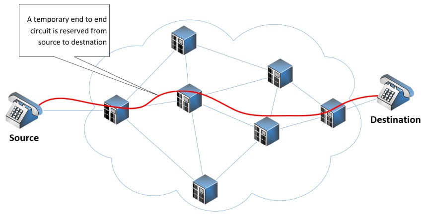
Circuit switching is a method of transmitting data over a network by creating an end-to-end dedicated circuit from the sender to the receiver.
The circuit exists for the duration of the communication session and is then torn down. An excellent example of a circuit-switched network is the traditional telephone network. The following diagram illustrates such a network:
Contrary to circuit switching, packet switching involves the separation of data into discrete packets that are sent individually across a network.
Each packet is composed of a header and payload. The header contains addressing and other control information, while the payload contains the contents of the data being sent.
Each packet is routed independently through the packet-switched network based on addressing information that is contained within the header.
This means that each packet may take a different path through different nodes to get to the destination depending upon the routing mechanisms used at each node, and the network conditions at the time.
As multiple packets reach their destination their payloads are reassembled and presented to the applications requiring the data. The following diagram shows how each packet is routed by each node along the path to reach its destination.
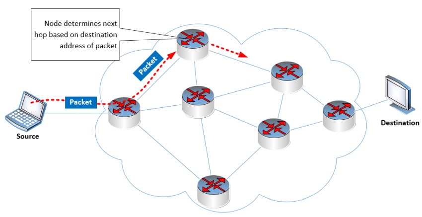
When a node receives a packet, it reads the destination address in the header, and based on its internal routing table, decides which exit interface the packet should be sent from. This is done at every node that receives the packet until it reaches the intended destination.
The success of this packet-switching arrangement depends upon the correctness of the routing table within each node.
The Routing Table
Let’s now shift the conversation to IP. When a router receives an IP packet, it reads the destination address in the header.
This destination address is compared with the entries found within the IP routing table. Once a match is found, the routing table indicates the exit interface that the packet should be sent out of. Take a look at this network diagram:
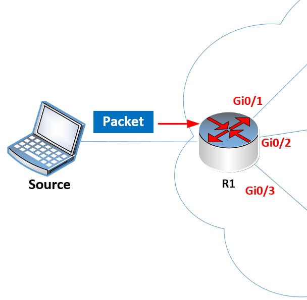
Imagine the source sends a packet with a destination IP address of 192.168.12.20. R1 will receive this packet and must decide out of which exit interface it will send it. Here is the routing table of R1:
R1#show ip route
Codes: L – local, C – connected, S – static, R – RIP, M – mobile, B – BGP
D – EIGRP, EX – EIGRP external, O – OSPF, IA – OSPF inter area
N1 – OSPF NSSA external type 1, N2 – OSPF NSSA external type 2
E1 – OSPF external type 1, E2 – OSPF external type 2
i – IS-IS, su – IS-IS summary, L1 – IS-IS level-1, L2 – IS-IS level-2
ia – IS-IS inter area, * – candidate default, U – per-user static route
o – ODR, P – periodic downloaded static route, H – NHRP, l – LISP
a – application route
+ – replicated route, % – next hop override, p – overrides from PfR
Gateway of last resort is not set
192.168.1.0/24 is variably subnetted, 2 subnets, 2 masks
C 192.168.1.0/24 is directly connected, GigabitEthernet0/1
L 192.168.1.254/32 is directly connected, GigabitEthernet0/1
S 192.168.2.0/24 [1/0] via 192.168.12.2
192.168.12.0/24 is variably subnetted, 2 subnets, 2 masks
C 192.168.12.0/24 is directly connected, GigabitEthernet0/2
L 192.168.12.1/32 is directly connected, GigabitEthernet0/2
Notice the red highlighted entry that states that the 192.168.12.0/24 network is directly connected to the GigabitEthernet0/2 interface. Since the destination address 192.168.12.20 falls within the range of this entry, the exit interface that will be used is Gi0/2.
Now the above routing table contains only a few entries of directly connected networks. In a large network, there should be dozens or even hundreds of routes in the routing table. How is the routing table created and maintained?
Populating the Routing Table
The key to successful IP routing is a correct routing table within each router. The routing table can either be statically configured (static routing), or it can be dynamically created and updated (using a dynamic routing protocol).
Using Static Routing
As a network administrator, you can configure a router with as many static routes as you like, indicating the proper exit interface that should be used for each individual destination network. Assuming you put in the correct information in the routing tables of all the routers in your topology, this will result in a correctly working network.
However, there are disadvantages to such an approach including a lack of scalability, difficulty in maintaining and administrating, prone to errors, as well as unreliable in the event of a failure in part of the network.
Using Routing Protocols
The preferred method of maintaining up-to-date and accurate routing tables is to use a routing protocol. Routing protocols can be used to dynamically populate the routing table of all the routers in a topology ensuring that IP packets will correctly be forwarded to the appropriate next hop router to successfully reach their intended destinations.
How Routing Protocols Work
Routing protocols define rules that routers can use to exchange information about the network they can reach.
A router automatically knows about the networks it is directly connected to because its interfaces are configured with IP addresses within those networks.
Routers will advertise these directly connected networks to their neighbors, allowing them to know how to reach them.
Their neighbors in turn advertise those networks to additional routers downstream until all the routers in a topology learn about each other’s directly connected networks and how to reach them.
All of the routing information received is automatically installed within the routing table of each device.
Routing protocols will periodically send updates to their neighbors to ensure that all the routing information is up to date.
If a network failure occurs, where a router may lose connectivity to one of its interfaces, a routing protocol update is triggered, where the local router will inform its neighbors that it is no longer able to reach that particular network.
This information ripples throughout the topology until all routers are aware of the change. This process of exchanging routing information until all of the routers’ routing tables are up to date is known as convergence.
If configured correctly, the application of routing protocols is much more scalable than static routing, and can dynamically change, enabling alternative routes to destinations, if they are available, in the event of a failure in one area of the network.
Some Examples of Dynamic Routing Protocols
Routing protocols fall into three primary types based on how they operate:
- Link state routing protocols – These protocols allow each node to create a complete map of the topology and the networks to which all nodes are connected. OSPF and IS-IS are two common link state routing protocols.
- Distance vector routing protocols – These protocols evaluate the best path based on the distance to the destination. Unlike link state protocols, distance vector protocols don’t create a full map of the topology, but maintain distance information to each destination. RIP and EIGRP are two common link state routing protocols.
- Path-vector routing protocols – These protocols maintain path information to each destination. BGP is a path vector routing protocol and is the de facto standard routing protocol used on the internet.
Purpose of Routing Protocols
Routing protocols play a pivotal role in the efficient functioning of computer networks by enabling communication between devices and ensuring the optimal path for data transmission.
They deliver scalability, ease of deployment, as well as redundancy in large IP networks. Various types of protocols are used in different scenarios, but for any large network, the deployment of a routing protocol is a must.
Related Posts
- Difference Between Routers and Switches in TCP/IP Networks
- 11 Different Types of IP Addresses Used in Computer Networks
- Compare and Contrast Network Topologies (Star, Mesh, Bus, Hybrid etc)
- 11 Networking Companies Like Cisco (Competitors)
- What is a Wildcard Mask – All About Wildcard Masks Used in Networking