A few months ago I was involved in a project where we had to design a network redundancy scenario with two physically separate networks in two different buildings (the sites were a few kilometers away from each other).
The main requirement was to provide Inbound Internet Access to two Server Pools (Linux Servers in High Availability Cluster). Traffic therefore would flow from the Internet to the Servers which were protected by two Cisco ASA Firewalls. The network has been implemented successfully and is working pretty good with no problems.
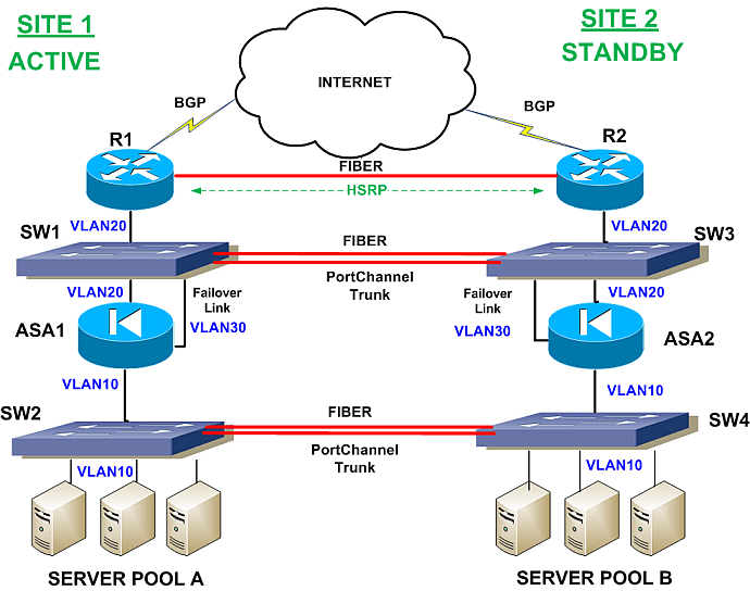
Let’s see the high level network diagram that we have designed below.
NOTE: In this article I will not provide all the details with configuration commands etc. The purpose is to describe the architecture designed in high level, so if you have any specific questions let me know in the comments section below this article.
Network Description
First of all, we have decided to go with ACTIVE/STANDBY approach in all elements of the network. SITE 1 is the ACTIVE network site and SITE2 is the STANDBY network site. During normal operation, traffic flows from the Internet towards SITE1 network in order to reach “SERVER POOL A”.
Starting from top to bottom, let me describe the main features and elements of the network.
Routers R1/R2
The public Interfaces of the routers are connected to the ISP for Internet access. BGP protocol is running between the routers and the ISP network. With BGP we arranged traffic to flow towards SITE1 as main path from the ISP.
A fiber link runs between the two routers to enhance certain failure scenarios and to facilitate better functioning of the HSRP mechanism.
The internal interfaces of R1/R2 are connected to two switches (SW1 and SW3 respectively). These two internal interfaces are connected to VLAN20 of both switches, so they belong in the same network subnet.
HSRP is configured between routers R1 and R2 with R1 being the active primary router in the HSRP group.
A static route for the SERVER POOL subnet was configured on the Routers. This static route points to the Active ASA outside IP.
Switches SW1/SW3
These are Layer2 switches connected with two fiber optic links. The two links are configured as PortChannel and Trunk. The trunk switchport mode is required so that all Vlans can pass between the two switches.
ASA1 and ASA2
The two ASA firewalls are configured in Active/Standby mode (ASA1 being the Active and ASA2 the Standby one).
Usually, when we configure ASA firewalls in a failover mode, both devices are physically located next to each other and are connected directly with a failover link. In our scenario above, we decided to separate the two devices in the two distant buildings. The failover links are communicating between them via the Layer2 switches (SW1/SW3) and the trunk fiber links. As you can see from the diagram above, both Failover Links belong to VLAN30, thus it is like being directly connected in the same Layer2 vlan.
Also, notice that the outside interfaces of ASA1/ASA2 belong to VLAN20 and the inside interfaces of the two ASAs belong to VLAN10 (same VLANs on both sites). Thus, both outside and inside ASA links have Layer 2 connectivity so that the failover mechanism will operate correctly.
The ASA configuration has a default route pointing to the Internal HSRP IP of R1/R2 router group.
Switches SW2/SW4
These are the internal Layer2 switches hosting the two SERVER POOLS as shown in the schematic diagram. Just like the other two switches on top (SW1/SW3), these two internal switches are connected with two fiber links which are configured as PortChannel and Switchport Trunk.
SERVER POOLS
I don’t know much about the actual configuration of the two Server groups, but I know that they are Linux based and they are using Linux High Availability cluster configuration. Basically they host the same services and are somehow synchronized between them.
Failover/Redundancy Scenarios
OK, I know that this is not a 99.999% failsafe network topology but it is relatively simple to implement, it provides good redundancy and works very well. Let’s see some failover scenarios and describe the traffic flow for each failover case.
NOTE: Since during normal operation all traffic flows through SITE1 devices, we will describe the failover cases whereby a network element of SITE1 has a failure.
1) Failure of Router R1
In this case, the HSRP mechanism will kick in and Router R2 will become the active device. Note that ASA1 is still active here.
Traffic flow for this case: Internet –> R2 –> SW3 –> ASA1 (through Fiber Links) –> SERVER POOL A
2) Failure of switch SW1
If the whole switch fails (e.g power failure and switched off), then both R2 and ASA2 will become active.
Traffic flow for this case: Internet –> R2 –> SW3 –> ASA2 –> SW4 –> SW2 –> SERVER POOL A
3) Failure of Firewall ASA1
If ASA1 fails, then ASA2 will become Active:
Traffic flow for this case: Internet –> R1 –> SW1 –> SW3 –> ASA2 –> SW4 –> SW2 –> SERVER POOL A
4) Failure of switch SW2
If the whole switch fails (e.g power failure and switched off), then ASA2 will become active. Also, Server Pool B will become active as well.
Traffic flow for this case: Internet –> R1 –> SW1 –> SW3 –> ASA2 –> SW4 –> SERVER POOL B
I hope you have found the above useful. With some modifications and careful planning you can implement similar network topologies with even more complicated traffic flows.
Related Posts
- Difference Between Routers and Switches in TCP/IP Networks
- 11 Different Types of IP Addresses Used in Computer Networks
- Compare and Contrast Network Topologies (Star, Mesh, Bus, Hybrid etc)
- 11 Networking Companies Like Cisco (Competitors)
- What is a Wildcard Mask – All About Wildcard Masks Used in Networking