Troubleshooting physical layer problems on UTP Ethernet cabling can sometimes be a nightmare. Dealing with patch cables is a snap, but what happens if your structured cabling has a fault, or if a newly created UTP cable results in intermittent connectivity? Further still, what if you don’t have direct access to the faulty cabling because you’re connected remotely?

Luckily, Cisco has some basic testing features on many of its platforms that allow you to do a quick and dirty physical check on the connected copper cabling.
This is an excellent front-line troubleshooting technique for determining where the problem lies. Specifically, this feature is the Time Domain Reflectometer (TDR) feature.
In this article we’ll explore the TDR capabilities of Cisco devices and describe also the Cisco command to test cables for faults etc.
What is TDR?
A time domain reflectometer is an electronic instrument used to locate faults in all types of copper cables. Below you can see an example of a sophisticated TDR device.
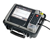
An advanced TDR device used for copper cable fault detection. (source)
A TDR works by transmitting an incident signal onto the conductor, and it then “listens” for the reflections of that signal.
The reflected signal is then recorded, analyzed, and displayed. The signal will have particular characteristics depending upon if there is a fault, and, if so, the nature of that fault.
The following diagram show some examples of the kind of reflections a TDR may record.
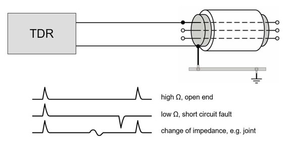
The reflected waveforms that will be recorded by a TDR under various circumstances (source)
The following further describes the above waveforms for a UTP cable:
- The first waveform indicates that the UTP cable is in good condition. The signal that is sent is reflected back and has the same form.
- The second waveform indicates a short circuit at the other end. This means that one of the wires is in contact with a second wire creating this short circuit, and thus the waveform returns with a negative amplitude.
- The third waveform indicates a discontinuity in the cable. This may be due to a kink in the cable that has resulted in a damaged wire, but not to the point where it is completely severed.
In addition to the above information, the time it takes for the reflected waveform to return also indicates the length of the cable, and the location of the discontinuity that may be encountered.
Dedicated TDR devices can be very sophisticated, giving many more details about the state of a copper cable, but they can also be quite expensive.
Cisco’s TDR feature
Cisco’s implementation of the TDR feature in many of its devices provides a scaled-down version of a full-blown TDR that delivers basic copper cable testing capabilities.
Using the same principles as those described above, a Cisco device can perform TDR testing on the cable connected to a particular port using the following command:
test cable-diagnostics tdr {interface {interface-number}}
This essentially initiates a standard set of TDR tests that are automatically run on the device. Such a test should take just a few seconds. The following is an example of the output of this command:
Router # test cable-diagnostics tdr interface gigabitethernet8/1
TDR test started on interface Gi8/1
A TDR test can take a few seconds to run on an interface
Use ‘show cable-diagnostics tdr’ to read the TDR results.
Once complete, as the informational message above indicates, you can use the following command to display the results of the last TDR test run on a particular interface:
show cable-diagnostics tdr {interface interface-number}
Here is an example of the output of such a command:
Router# show cable-diagnostics tdr interface gigabitethernet 8/1
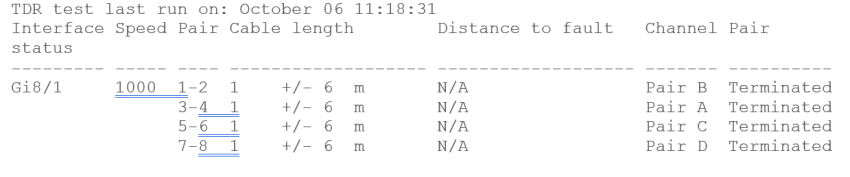
Note that the results are given on a per-pair basis. The information in the output includes:
- The date of the last TDR test run on this interface
- The tested interface
- The line speed of the interface
- The local pair name
- The cable length with an estimate of the accuracy shown as +/- in meters
- If there is a fault, the distance to that fault is indicated
- The pair designation indicated by the Channel column
Arguably, the most important information displayed is that in the last column. This column may have any number of results including:
- Terminated – This indicates that the link is up. This is the desired output that shows that all is working as it should be.
- Shorted – A short circuit is detected.
- Open – An opening or a break is detected on the cable
- Not Completed – The TDR test failed.
- Not Supported – The TDR test is not supported on the port type. This may be seen on a fiber or serial link.
- Broken – The pair is either open or shorted.
- ImpedanceMis – the impedance is mismatched. This may indicate a problem on the remote device rather than on the cable itself.
- InProgress – The diagnostic test has not yet been completed.
Guidelines and Caveats
There are some important things to keep in mind before performing a TDR test. These include:
- TDR works best if the test cable is disconnected from the remote port, otherwise the results may be difficult to interpret. However, this is not always immediately possible.
- When performed on a cable that is connected to a FastEthernet port on the remote end, the unused pairs 4-5 and 7-8 appear to be faulty because the remote end does not terminate those pairs.
- TDR treats each pair of wires as a single entity and identifies problems on a per-pair basis rather than a per-wire basis.
Supported Cisco platforms
Among the devices that support the TDR function include but are not limited to:
- Catalyst 2960 series
- Catalyst 3560G
- Catalyst 3750 series
- Cisco 7600 Routers
- Nexus 7K series
The IOS versions that support TDR are 12.2(17a) and later. However, for a complete and verified list of supported platforms and IOS versions, look at the Cisco Feature Navigator.
Conclusion
Using the TDR feature on supported Cisco devices is an excellent first step in diagnosing possible problems on the Physical Layer.
It can be performed in seconds, and remotely, and thus requires very little effort. Just keep in mind that the results should be used only as a first step to determine the most appropriate next steps for your troubleshooting procedure.
Useful links:
- Command Reference – test cable-diagnostics tdr
- Command Reference – show cable-diagnostics tdr
- Checking Port Status and Connectivity on a Cisco Device
Related Posts
- Failure-Mode Engineering: Turning Network Adversity Into an Advantage
- What is Cisco Virtual Port Channel (vPC) – Explained and Discussed
- What is a Wildcard Mask – All About Wildcard Masks Used in Networking
- Configuration Drift? Not on our Watch in Networks
- What is Cisco Identity Services Engine (ISE)? Use Cases, How it is Used etc