Link aggregation is a technique used in networking to bundle multiple physical ports on a network device to operate as a single link. The aggregated link acts as a single logical port functioning at a speed equal to the sum of the bandwidths of all of the physical links.
In this article, we’ll further explore this technique, explain how it works, examine under what conditions it is useful, and identify some of the important caveats involved with its use.
We will also examine some simple configuration examples on Cisco devices, to see how to implement it.
What is LAG?
Link aggregation, sometimes referred to as LAG, which stands for Link Aggregation Groups, refers to the feature of network devices that allow the combining of multiple physical network connections in parallel to increase throughput and provide redundancy.
This technique is also known as bonding, teaming, port channeling, or link bundling. In the context of Cisco, the feature of LAG is called an EtherChannel.
These terms may be used interchangeably in the context of the technology, and within this article as well.
Common Use Cases
LAG use cases are primarily used within datacenters between switches where redundancy and higher throughput are required.
They are also often used to deliver high-bandwidth redundant connectivity to servers and storage area networks (SANs).
Network backbone connections, and carrier and ISP networks and any network where increased bandwidth and fault tolerance are needed, are also excellent candidates for the use of LAG.
How Link Aggregation Works
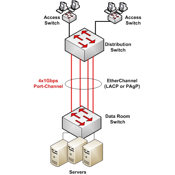
The primary function of LAG is to combine multiple network links between two devices into one logical link.
This combination leads to the aggregation of bandwidth from each physical link, resulting in a higher throughput.
For example, if four 1Gbps links are combined into a LAG, the total available bandwidth would be 4Gbps.
Supported Devices
LAG can be implemented between various types of network devices. Multiple links between switches can be bundled, and this is often the most common usage of the technology.
Some other topologies also include the bundling of multiple network interface cards (NICs) on a particular server, enabling redundant links to network devices.
Somewhat less common is the implementation of LAG on a router, but it can be done if supported.
Configuration Options: Static vs. Dynamic
LAG can be configured either statically or dynamically.
Static LAG
Static LAG involves manually configuring each end of the aggregated links. While it is simpler to set up, it lacks the dynamic negotiation capabilities, and the redundancy checks that LAG protocols offer.
Static LAG is less commonly used due to its limitations in larger, more dynamic network environments.
Dynamic LAG with Protocols
Dynamic LAG configurations use protocols like Link Aggregation Control Protocol (LACP) and Port Aggregation Protocol (PAgP) to manage the bundling of links.
These protocols allow the connected devices to negotiate the establishment of LAGs and will also detect if there are any misconfigurations on either end of the LAG. Here’s a little more detail about these particular protocols:
- LACP (IEEE 802.3ad): This is a standard protocol that provides a method of controlling the bundling of several physical ports together to form a single logical channel. LACP allows a network device to negotiate an automatic bundling of links by sending LACP packets to the peer.
- PAgP: This is a Cisco-proprietary protocol similar to LACP. It facilitates the automatic creation of fast Ethernet channeling links.
Load Balancing Mechanisms
Load balancing across LAGs is a critical feature that optimizes the distribution of network traffic across multiple physical links.
This process enhances both the efficiency and capacity of network connections. The primary goal of load balancing in LAG is to evenly distribute incoming and outgoing traffic among all the available physical links in the aggregation group.
This not only maximizes bandwidth utilization but also ensures no single link becomes a bottleneck.
Load-balancing algorithms divide network traffic into flows. Each flow is then assigned to one of the links in the LAG. A flow can be based on various parameters like source/destination IP addresses, MAC addresses, TCP/UDP ports, or a combination of these.
Once a flow is mapped to a particular link, it typically stays on that link as long as the number of links and the load-balancing algorithm do not change. This consistency is crucial for maintaining the order of packets within each flow.
The specific algorithm used for load balancing can be configured and adjusted as needed.
Layer 2 VS Layer 3 EtherChannel
On a Cisco device, it is possible to configure EtherChannel as a logical Layer 2 interface or a logical Layer 3 interface.
In the former case, the logical interface is configured either as an access port or as a trunk port, with all of the associated configuration parameters in each instance.
In the latter case, the logical interface is configured with an IP address, thus making it a routed logical port.
The support for Layer 2 or Layer 3 EtherChannel will depend upon the platform on which it is being configured, and the IOS version of that platform.
Configuration Requirements
When configuring LAG, the following restrictions and guidelines must be adhered to:
- On most Cisco switches, up to 16 physical interfaces can be included within an LAG, but only 8 interfaces will be active at any one time.
- On most Cisco routers, up to four physical ports can be included within an LAG.
- All physical interfaces belonging to a particular LAG must be configured with the same parameters including duplex, speed, native and allowed VLANs, as well as switchport modes (access or trunk).
Example Configuration: Layer 2 EtherChannel using LACP
Configuring LACP on a Cisco switch involves defining the ports that you want to aggregate and assigning them to a channel group. Here’s a basic example:
Switch# configure terminal
Switch(config)# interface range GigabitEthernet0/1 – 2
Switch(config-if-range)# channel-group 1 mode active
Switch(config-if-range)# exit
Switch(config)# interface Port-channel 1
Switch(config-if)# switchport mode trunk
Switch(config-if)# exit
In this example, we are aggregating GigabitEthernet ports 0/1 and 0/2 into a channel group 1.
The mode active command enables LACP actively on these ports. The Port-channel 1 is the logical interface representing the aggregated links.
As you can see, the Port-channel 1 logical interface has been configured as a trunk. Note that the configuration on the other end of the link must also be configured accordingly for successful EtherChannel operation.
Useful links
This article only scratches the surface concerning this feature. For more information, take a look at the following Cisco documentation to learn more about the technology and how it can be implemented:
- Configuring EtherChannel on Cisco 2950 Switch
- Configuring EtherChannel on Cisco Integrated Services Routers (ISRs)
Although the documentation is specific for particular models, the principles of EtherChannel are common across all Cisco devices.
Conclusion
Link Aggregation Groups in Cisco environments are a critical component in designing efficient, high-capacity, and reliable networks.
Whether configured statically or dynamically with protocols like LACP or PAgP, LAGs offer significant benefits in terms of bandwidth aggregation and redundancy.
Understanding and implementing LAGs can markedly improve network performance and resilience in a Cisco-based infrastructure.
Related Posts
- Difference Between Routers and Switches in TCP/IP Networks
- 11 Different Types of IP Addresses Used in Computer Networks
- Compare and Contrast Network Topologies (Star, Mesh, Bus, Hybrid etc)
- 11 Networking Companies Like Cisco (Competitors)
- What is a Wildcard Mask – All About Wildcard Masks Used in Networking