The OSPF (Open Short Path First) dynamic routing protocol is probably the most popular and most used IGP routing protocol in TCP/IP networks.
Because OSPF is supported by all networking vendors, it does not have the restrictions of proprietary protocols like Cisco EIGRP for example (in terms of multi-vendor environments etc).
The new Cisco CCNA exam (200-301) requires knowledge of OSPF (specifically OSPFv2 in single Area configuration), which shows the importance that Cisco places in this dynamic routing protocol.
Importance of DR/BDR
One of the concepts that you need to learn about OSPF is DR/BDR election in broadcast network types (multi-access network such as Ethernet LAN).
So, if two or more routers are connected on a broadcast network (e.g an Ethernet LAN) and are configured for OSPF, they must select a DR (Designated Router) and a BDR (Backup Designated Router).
Note that DR/BDR is done on a per-segment basis and NOT on per-area basis.
All routers in the broadcast network must form an OSPF adjacency with all other routers. The goal of DR and BDR is to reduce the complexity of the multi-access network from a link state database point-of-view.
The DR/BDR act as central points of exchanging link-state information instead of having to exchange info with all other routers in the broadcast network (mesh). This reduces greatly the link-state database of routers.
Note that there is no DR/BDR elected in point-to-point networks (e.g on serial links).
Factors affecting DR/BDR Election
There are two factors that influence DR/BDR election:
- Router ID: The Router ID is the highest IP address of the device or the highest IP address among loopback addresses (if one is configured) on the Cisco router or can be configured manually by “router-id a.b.c.d” command under the OSPF process.
- OSPF Priority: This is by default 1 for all routers. The OSPF priority is configured per interface.
Selection Rules for DR/BDR
- The router with the highest OSPF Priority on a specific segment (router interface) will become the DR.
- In case of a tie (i.e same OSPF Priority), the router with the highest Router ID will become the DR. The next biggest Router ID will become the BDR.
Since by default all routers have OSPF Priority of 1, it means that the router which has the highest IP address (i.e highest Router ID) will become the DR.
We can influence the election of DR and BDR by configuring explicit Router ID or OSPF priority on the routers.
Configuration Example
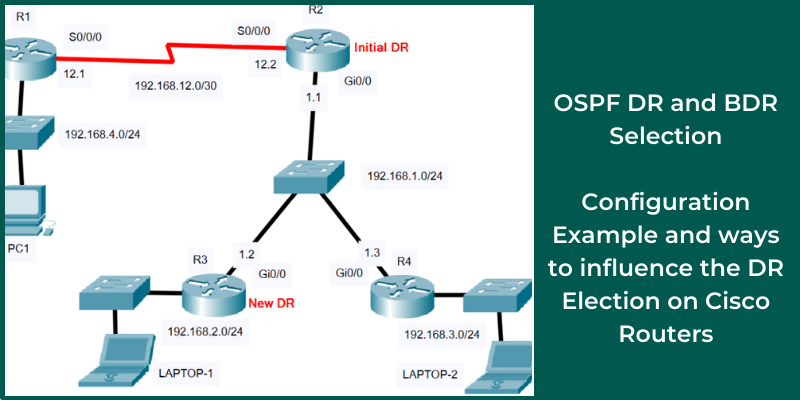
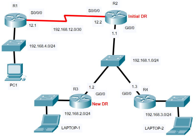
Let’s see an example topology below with 4 routers (R1 connected to R2 via point-to-point link and R2, R3, R4 connected to a broadcast multi-access network).
Step 1: Configure IP Addresses on Routers
R1#conf t
R1(config)#interface serial 0/0/0
R1(config-if)#ip address 192.168.12.1 255.255.255.252
R1(config-if)#clock rate 2000000
R1(config-if)#no shut
R1(config-if)#exit
R1(config)#interface GigabitEthernet0/0
R1(config-if)#ip address 192.168.4.1 255.255.255.0
R1(config-if)#no shut
R1(config-if)#exit
R1(config)#
R2#conf t
R2(config)#interface serial 0/0/0
R2(config-if)#ip address 192.168.12.2 255.255.255.252
R2(config-if)#no shut
R2(config-if)#exit
R2(config)#interface GigabitEthernet0/0
R2(config-if)#ip address 192.168.1.1 255.255.255.0
R2(config-if)#no shut
R2(config-if)#exit
R2(config)#
R3#conf t
R3(config)#interface GigabitEthernet0/0
R3(config-if)#ip address 192.168.1.2 255.255.255.0
R3(config-if)#no shut
R3(config-if)#exit
R3(config)#interface GigabitEthernet0/1
R3(config-if)#ip address 192.168.2.1 255.255.255.0
R3(config-if)#no shut
R3(config-if)#exit
R3(config)#
R4#conf t
R4(config)#interface GigabitEthernet0/0
R4(config-if)#ip address 192.168.1.3 255.255.255.0
R4(config-if)#no shut
R4(config-if)#exit
R4(config)#interface GigabitEthernet0/1
R4(config-if)#ip address 192.168.3.1 255.255.255.0
R4(config-if)#no shut
R4(config-if)#exit
R4(config)#
Step 2: Configure All Routers in OSPF Area 0
R1(config)#router ospf 1
R1(config-router)#network 192.168.12.0 0.0.0.3 area 0
R1(config-router)#network 192.168.4.0 0.0.0.255 area 0
R1(config-router)#end
R1#wr
R2(config)#router ospf 1
R2(config-router)#network 192.168.12.0 0.0.0.3 area 0
R2(config-router)#network 192.168.1.0 0.0.0.255 area 0
R2(config-router)#end
R2#wr
R3(config)#router ospf 1
R3(config-router)#network 192.168.1.0 0.0.0.255 area 0
R3(config-router)#network 192.168.2.0 0.0.0.255 area 0
R3(config-router)#end
R3#wr
R4(config)#router ospf 1
R4(config-router)#network 192.168.1.0 0.0.0.255 area 0
R4(config-router)#network 192.168.3.0 0.0.0.255 area 0
R4(config-router)#end
R4#wr
Step 3: Verification – DR/BDR – Neighbor Adjacencies
R1#show ip ospf neighbor
Neighbor ID Pri State Dead Time Address Interface
192.168.12.2 0 FULL/ – 00:00:35 192.168.12.2 Serial0/0/0
The above shows the OSPF neighbor of R1 which (as shown in our diagram) is router R2 with Neighbor ID “192.168.12.2”.
The Neighbor ID is the Router ID of the neighbor router. The Router ID is the highest IP address of the device or the highest IP address among loopback addresses (if one is configured) on the Cisco router or can be configured manually by “router-id a.b.c.d” command under the OSPF process.
The “State” shows that this router has established a “FULL” OSPF relationship with the neighbor router. This is the normal state for an OSPF router.
R1#show ip ospf interface serial 0/0/0
Serial0/0/0 is up, line protocol is up
Internet address is 192.168.12.1/30, Area 0
Process ID 1, Router ID 192.168.12.1, Network Type POINT-TO-POINT, Cost:64
Transmit Delay is 1 sec, State POINT-TO-POINT,
[output omitted]
The above shows that the OSPF network type running on the Serial Interface is “Point-to-Point”. Moreover, the Router ID of R1 is “192.168.12.1”.
R2#show ip ospf neighbor
Neighbor ID Pri State Dead Time Address Interface
192.168.3.1 1 FULL/BDR 00:00:38 192.168.1.3 GigabitEthernet0/0
192.168.2.1 1 FULL/DROTHER 00:00:38 192.168.1.2 GigabitEthernet0/0
192.168.12.1 0 FULL/ – 00:00:38 192.168.12.1 Serial0/0/0
Router R2 connects to both a Point-to-Point connection link (Serial Interface to R1) and also to a Multi-Access Network (Broadcast Domain) via interface Gi0/0 which connects via an Ethernet switch (Broadcast network) to the other routers R3 and R4.
As explained above, Routers connected to a Multi-Access network (such as Ethernet), will elect a DR (Designated Router) and a BDR (Backup Designated Router). A router that is not elected a DR or a BDR is called a DROTHER.
The router with the Highest OSPF Priority value will become the DR. In the event that the priorities are the same (Default priority is 1 for all routers), the Router ID becomes the tie breaker. The router with the highest Router ID (Neighbor ID- 192.168.12.2) becomes the DR. The router with the next biggest IP (Neighbor ID-192.168.3.1) becomes the BDR.
In our topology above, Router R2 will be elected to be the DR because it has the highest Router ID of 192.168.12.2. Moreover, Router R3 will be the BDR because it has the next highest Router ID of 192.168.3.1.
R2#show ip protocols
Routing Protocol is “ospf 1”
[output omitted]
Router ID 192.168.12.2
R2#show ip ospf interface gigabitEthernet 0/0
GigabitEthernet0/0 is up, line protocol is up
Internet address is 192.168.1.1/24, Area 0
Process ID 1, Router ID 192.168.12.2, Network Type BROADCAST, Cost: 1
Transmit Delay is 1 sec, State DR, Priority 1
Designated Router (ID) 192.168.12.2, Interface address 192.168.1.1
Backup Designated Router (ID) 192.168.3.1, Interface address 192.168.1.3
Timer intervals configured, Hello 10, Dead 40, Wait 40, Retransmit 5
Hello due in 00:00:00
Index 1/1, flood queue length 0
Next 0x0(0)/0x0(0)
Last flood scan length is 1, maximum is 1
Last flood scan time is 0 msec, maximum is 0 msec
Neighbor Count is 2, Adjacent neighbor count is 2
Adjacent with neighbor 192.168.3.1 (Backup Designated Router)
Adjacent with neighbor 192.168.2.1
Suppress hello for 0 neighbor(s)
In our example above, Router R2 has Router ID of 192.168.12.2 which is the highest Router ID in the Multi-Access network (BROADCAST type), thus R2 will be elected as the DR in OSPF. Moreover, the BDR has Router ID of 192.168.3.1.
R3#show ip ospf neighbor
Neighbor ID Pri State Dead Time Address Interface
192.168.3.1 1 FULL/BDR 00:00:36 192.168.1.3 GigabitEthernet0/0
192.168.12.2 1 FULL/DR 00:00:36 192.168.1.1 GigabitEthernet0/0
The above shows the OSPF neighbors of R3. This router has established FULL OSPF relationships with the BDR Router (192.168.3.1) and with the DR Router (192.168.12.2).
R4#show ip ospf neighbor
Neighbor ID Pri State Dead Time Address Interface
192.168.2.1 1 FULL/DROTHER 00:00:36 192.168.1.2 GigabitEthernet0/0
192.168.12.2 1 FULL/DR 00:00:36 192.168.1.1 GigabitEthernet0/0
The above shows the OSPF neighbors of R4. This router has established FULL OSPF relationships with router 192.168.2.1 that is not a DR/BDR (DROTHER) and with the DR Router (192.168.12.2).
Configure OSPF Priority and Router ID for DR Election
Let’s now see how to influence the DR election by changing either the OSPF Priority or the Router ID:
As seen in the previous section, Router R2 is elected as the DR because it has the highest Router-ID (192.168.12.2) and since OSPF priority is by default 1 on all routers, this means that R2 will be the DR.
We can influence the DR election by using two methods (as explained above):
1) Configure a higher Router-ID than any other router in the network.
2) Configure OSPF priority bigger than 1 (the default).
We will select R3 to become the new DR elected router by changing the above parameters.
Change DR Election with Router-ID
Let’s modify the Router-ID on R3 to make it bigger:
R3#conf t
R3(config)#router ospf 1
R3(config-router)#router-id 192.168.255.1
Reload or use “clear ip ospf process” command, for this to take effect
R3(config-router)#end
R3#clear ip ospf process
Reset ALL OSPF processes? [no]: yes
After setting the Router-ID of R3 (as 192.168.255.1), you will get a message that you need to reload all routers or run the command “clear ip ospf process” for this to take effect. This new Router-ID is the highest IP number in the whole network, therefore R3 will become the new DR.
Let’s now see which router is the new DR:
R3#show ip ospf interface gigabitEthernet 0/0
GigabitEthernet0/0 is up, line protocol is up
Internet address is 192.168.1.2/24, Area 0
Process ID 1, Router ID 192.168.255.1, Network Type BROADCAST, Cost: 1
Transmit Delay is 1 sec, State DR, Priority 1
Designated Router (ID) 192.168.255.1, Interface address 192.168.1.2
Backup Designated Router (ID) 192.168.3.1, Interface address 192.168.1.3
From above, you can see that R3 has been elected as the new DR router.
R2#show ip ospf neighbor
Neighbor ID Pri State Dead Time Address Interface
192.168.255.1 1 FULL/DR 00:00:38 192.168.1.2 GigabitEthernet0/0
192.168.3.1 1 FULL/BDR 00:00:39 192.168.1.3 GigabitEthernet0/0
192.168.12.1 0 FULL/ – 00:00:38 192.168.12.1 Serial0/0/0
Now, looking from router R2 perspective above, you can see that the new DR router has Neighbor ID (Router-ID) of 192.168.255.1 which is the one configured on Router R3.
Change DR Election using OSPF priority
Let’s now see how to influence DR election by increasing the OSPF priority on the interface of R3. We will change the OSPF priority on interface GigEthernet0/0 which is the one connected to the multi-access network.
First, let’s remove the Router-ID from R3:
R3#conf t
R3(config)#router ospf 1
R3(config-router)#no router-id 192.168.255.1
R3(config-router)#end
R3#wr
R3#reload
Note: It is better to reload all other routers as well.
If you run “show ip ospf neighbor” on R3 you will see that the DR now is again router R2 as before.
Now, let’s configure an OSPF priority on R3 which must be higher than 1 (the default):
R3#conf t
R3(config)#interface GigabitEthernet0/0
R3(config-if)#ip ospf priority 10
R3(config-if)#end
R3#clear ip ospf process
Let’s verify again which is the new DR router:
R2#show ip ospf neighbor
Neighbor ID Pri State Dead Time Address Interface
192.168.3.1 1 FULL/BDR 00:00:39 192.168.1.3 GigabitEthernet0/0
192.168.2.1 10 FULL/DR 00:00:33 192.168.1.2 GigabitEthernet0/0
192.168.12.1 0 FULL/ – 00:00:30 192.168.12.1 Serial0/0/0
From Router R2, you can see that the DR is now R3 (192.168.2.1) with a Priority (Pri) of 10.
Related Posts
- How to Configure Port Forwarding on Cisco Router (With Examples)
- Redistribution and OSFP – Discussion With Cisco Commands Examples
- Cisco HSRP States and Troubleshooting (With Commands)
- Cisco Router Login – GUI Login and How to Secure Your Access
- Route Filtering and OSPF – Workaround With Distribute List Filtering