The Border Gateway Protocol (BGP) is considered to be the routing protocol of the Internet because it runs between Internet Service Providers (ISPs) to interconnect all Autonomous Systems (AS) comprising the whole internet.
Of course the above refers to External BGP (eBGP) which runs between different Autonomous Systems. There is also another “flavor” of BGP which is Internal BGP (iBGP) and runs between routers in the same Autonomous System (e.g between the routers of the same ISP or enterprise network).
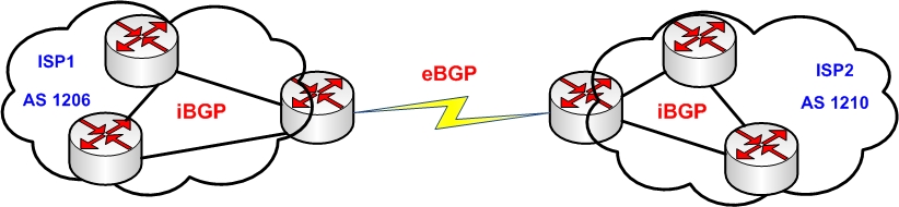
The diagram below illustrates a high level network topology connecting two different Autonomous Systems (e.g two ISPs) namely AS 1206 and AS 1210.
The routing protocol running between the two border gateways of the Autonomous Systems is eBGP. On the other hand, the routing protocol running within each AS is iBGP.
Unlike the other well known interior gateway protocols (like OSPF, RIP etc), BGP uses TCP to communicate between peer routers.
The TCP port 179 is used between two peer routers for BGP communication whereas the other routing protocols (OSPF, RIP, EIGRP etc) use multicast addresses for communication.
In this article we will discuss eBGP and iBGP and their differences and also we will see some basic configurations and troubleshooting commands on Cisco routers.
iBGP explanation and configuration
In iBGP, neighbors are connected with each other in the same autonomous system (AS) as we said above. iBGP neighbors don’t need to be directly connected with each other, but must be in the same AS and have TCP communication between them.
Another point to mention for iBGP, a route learnt from an iBGP peer will not be passed on to another iBGP peer by default. This restriction is in place for loop prevention within the same AS. The default Administrative Distance for iBGP peers is 200.
iBGP Basic Configuration
iBGP can be configured with the following commands.
Step1: enable global BGP process
Router(config)# router bgp [ASN]
Step2: establish the peering relationship
Router(config-router)# neighbor [IP address] remote-as [ASN]
The ASN mentioned above must be the same between the peer routers because they are in the same AS number.
Step3: Add the networks to be advertised by iBGP
Router(config-router)# network [network-number] mask [network-mask]
Step4: Verify the BGP peering communication:
Router# show ip bgp summary
Router# show ip bgp
Router# show ip route bgp
Let’s see an actual iBGP configuration example below:
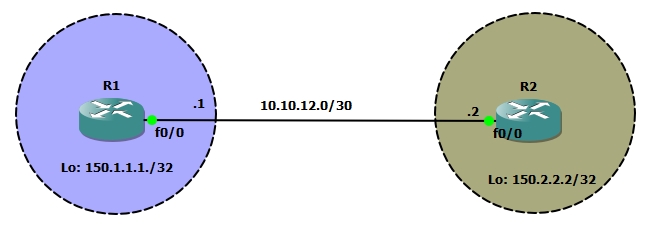
In this design we are going to configure iBGP peer relationship between R1 and R2. We have configured loopback 0 interfaces on R1 and R2 with IP address 150.1.1.1/32 and 150.2.2.2/32 respectively and we want to advertise these prefixes into BGP with network command under the BGP routing process.
R1 Configuration:
R1(config-if)#router bgp 10
R1(config-router)#neighbor 10.10.12.2 remote-as 10
R1(config-router)#network 150.1.1.1 mask 255.255.255.255
R2 Configuration:
R2(config)#router bgp 10
R2(config-router)#neighbor 10.10.12.1 remote-as 10
R2(config-router)#network 150.2.2.2 mask 255.255.255.255
*Mar 10 18:40:09.499: %BGP-5-ADJCHANGE: neighbor 10.10.12.1 Up
We can see that as soon as we configure the neighbor command on R2, the peer relationship of R2 with 10.10.12.1 (IP address of R1) goes up.
BGP Verification commands
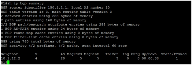
Next step is to verify the BGP configuration with “show ip bgp summary” command.
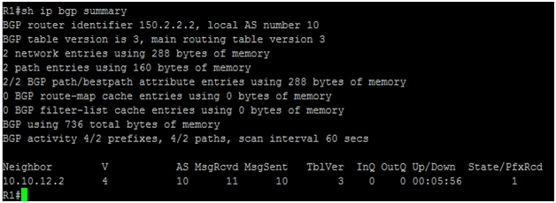
By issuing the “show ip bgp summary” command we can see under neighbor column the IP address 10.10.12.2. This is the IP address of R2 with which R1 has established the peering relationship.
We can see also that local AS number is 10. This means that both R1 and R2 are iBGP neighbors with each other, since the AS is the same. The number “1” under column state/PfxRcd means that R1 has successfully learned one prefix from R2 (150.2.2.2/32). Same is the case on R2 side.
Next step is to issue the “show ip bgp” command. This command will show us the topology table.
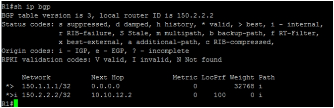
We can see from the above topology table that contains two network prefixes, 150.1.1.1/32 and 150.2.2.2/32.
The next hop 0.0.0.0 for prefix 150.1.1.1/32 tells us that this prefix has originated locally by R1. The next hop 10.10.12.2 for 150.2.2.2/32 tells us that this prefix originated from peer R2 router.
By default, iBGP has weight value set to 32768. We can also guess from the weight value that this is iBGP peer.
Next step is to verify the routing table for iBGP with “show ip route bgp” command.
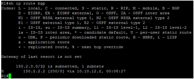
We can see that R1 has learned about 150.2.2.2 via 10.10.12.2 with Administrative Distance (AD) of 200.
BGP Loopback Interfaces:
An iBGP peer configured using a loopback interface is useful where we have multiple paths to the same destination, so in case one path goes down the neighbor stays up as it is independent of interfaces in that case (the loopback interface never goes down).
In example design below, we have two paths between R1 and R2. There are two Ethernet interfaces connecting the two peers, that is fastethernet 0/0 and fastethernet 1/0. The best option here is to use Loopback interfaces to establish the BGP neighbor peering.
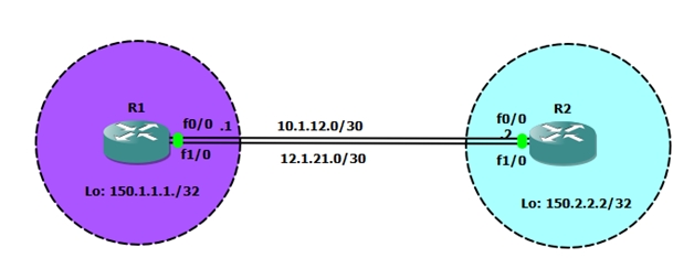
We know that BGP (EBGP/IBGP) peer relationships can be configured first by testing TCP reachability between the IP addresses of the two points, so we need to configure two static routes between R1 and R2 to reach loopback IP address of R1 and R2 before configuring the BGP peer relationship.
R1(config)#ip route 150.2.2.2 255.255.255.255 f 0/0
R1(config)#ip route 150.2.2.2 255.255.255.255 f 1/0 10
R2(config)#ip route 150.1.1.1 255.255.255.255 f0/0
R2(config)#ip route 150.1.1.1 255.255.255.255 f1/0 10
We are now able to reach loopback interfaces of R1 and R2. Let’s configure peer relationships between these routers using their loopback interfaces.
R1(config)#router bgp 10
R1(config-router)#no neighbor 10.1.12.2 remote-as 10
R1(config-router)#neighbor 150.2.2.2 remote-as 10
R1(config-router)#neighbor 150.2.2.2 update-source loopback 0
R1(config-router)#network 150.1.1.1 mask 255.255.255.255
R2(config)#router bgp 10
R2(config-router)#no neighbor 10.1.12.1 remote-as 10
R2(config-router)#neighbor 150.1.1.1 remote-as 10
R2(config-router)#neighbor 150.1.1.1 update-source loopback 0
R2(config-router)#network 150.2.2.2 mask 255.255.255.255
We can verify the configuration with same verification commands used previously.
EBGP explanation and configuration:
In eBGP, neighbors are connected with each other in different autonomous systems (AS). The EBGP neighbors need to be directly connected to each other.
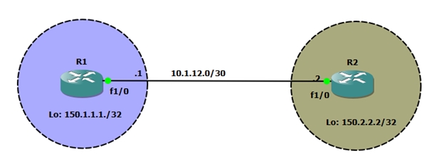
In this design we have R1 and R2 connected with each other via EBGP peering. R1 is in AS#10 whereas R2 is in AS#20.
Let’s see the basic configuration for eBGP on both routers.
R1 Configuration:
R1(config-if)#router bgp 10
R1(config-router)#neighbor 10.1.12.2 remote-as 20
R1(config-router)#network 150.1.1.1 mask 255.255.255.255
R2 Configuration:
R2(config)#router bgp 20
R2(config-router)#neighbor 10.1.12.1 remote-as 10
R2(config-router)#network 150.2.2.2 mask 255.255.255.255
*Mar 11 17:42:01.403: %BGP-5-ADJCHANGE: neighbor 10.1.12.1 Up
As soon as we configure R2, neighbor relationship came up. We can verify the configuration with same commands as we executed for iBGP peering.
Next step is to verify the BGP neighbor relationship with “show ip bgp summary” command.
We can see from the screenshot above that neighbor relationship has been established with 10.1.12.2. The local AS number is 10, whereas the AS number under AS column is 20, which means the two routers are connected with each other via eBGP.
Next step is to verify the topology table using “show ip bgp”
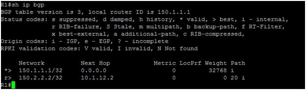
The topology table of R1 shows that next hop of 150.1.1.1/32 is 0.0.0.0 with weight set to 0, meaning it is a locally generated route.
The next hop for 150.2.2.2/32 is 10.1.12.2 meaning the route has been learned from R2. We can see AS number 20 under path column for 150.2.2.2/32, which is the AS number from where this prefix is learned.
The final step for verification is to check the routing table using “show ip route bgp” command.
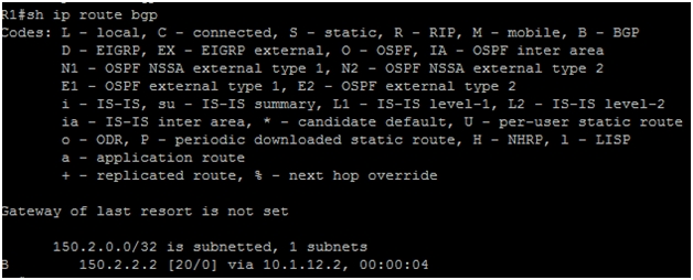
We can see that 150.2.2.2 is learned via 10.1.12.2 with AD of 20 (Administrative Distance for eBGP peer).
Related Posts
- How to Configure Port Forwarding on Cisco Router (With Examples)
- Redistribution and OSFP – Discussion With Cisco Commands Examples
- Cisco HSRP States and Troubleshooting (With Commands)
- Cisco Router Login – GUI Login and How to Secure Your Access
- Route Filtering and OSPF – Workaround With Distribute List Filtering