In this configuration tutorial I will show you how to configure a GRE tunnel between two Cisco IOS routers. One of the routers is located behind a Cisco ASA 5500 Firewall, so I will show you also how to pass GRE traffic through a Cisco ASA as well.
As you might know already, GRE tunnel termination is not supported on Cisco ASA firewalls. However, this is fully supported on Cisco routers.
GRE tunnels are not secure (no traffic encryption takes place through GRE (except if you run GRE over IPSEC).
However, GRE tunnels are useful in cases where we need to pass “non-unicast” traffic between two remote sites (e.g through the Internet).
Two scenarios that come to my mind now include passing routing protocols (such as OSPF) between two remote sites, and also passing multicast traffic through the GRE tunnel from one site to another.
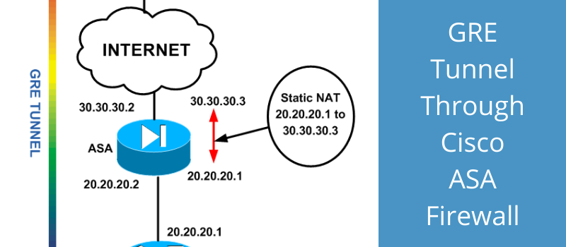
We will be using the following network diagram:

As shown from the diagram above, we have two remote sites (LAN1 and LAN2) which we need to connect through the Internet via a GRE tunnel.
The GRE tunnel will be terminated between routers R1 and R2. When configuring GRE, a virtual Layer3 “Tunnel Interface” must be created.
The GRE tunnel will be running between the two Tunnel Interfaces (10.0.0.1 and 10.0.0.2 as shown from diagram).
Also, the Tunnel Interfaces will be using as actual source IPs the addresses of the outside router interfaces (20.20.20.1 for R1 and 50.50.50.1 for R2). Therefore, IP routing reachability must be in place between 20.20.20.1 and 50.50.50.1.
As shown, router R1 is behind a Cisco ASA firewall. This is exactly what makes this scenario a little bit different from others.
Since R2 must be able to reach R1, the only way to “expose” R1 to the outside world is by creating a static NAT on the ASA firewall.
The static NAT rule will translate 20.20.20.1 (R1 outside IP) to an outside public IP, let’s say 30.30.30.3.
Therefore, R2 will be able to reach R1 via 30.30.30.3 public IP. Also, we must configure an access list on the ASA (applied on the outside ASA interface) which must allow GRE traffic from 50.50.50.1 to 20.20.20.1
Configuration
Lets see the configuration, starting with the routers first:
ROUTER R1
!First configure IP addresses on R1
interface FastEthernet0/0
ip address 192.168.1.1 255.255.255.0
duplex auto
speed auto
!
interface FastEthernet1/0
ip address 20.20.20.1 255.255.255.0
duplex auto
speed auto
!Default route towards ASA
ip route 0.0.0.0 0.0.0.0 20.20.20.2
!Now configure GRE Tunnel Interface. Note that we reduce the MTU size in order to accommodate the extra headers added from the GRE protocol.
interface Tunnel0
ip address 10.0.0.1 255.255.255.0
ip mtu 1400
ip tcp adjust-mss 1360
tunnel source 20.20.20.1
tunnel destination 50.50.50.1
!
!Now tell the router that remote subnet of LAN2 can be reached via the GRE endpoint 10.0.0.2
ip route 192.168.2.0 255.255.255.0 10.0.0.2
Now let’s move on to configuring R2.
ROUTER R2
!First configure IP addresses on R2
interface FastEthernet0/0
ip address 192.168.2.1 255.255.255.0
duplex auto
speed auto
!
interface FastEthernet1/0
ip address 50.50.50.1 255.255.255.0
duplex auto
speed auto
!Default route towards ISP
ip route 0.0.0.0 0.0.0.0 50.50.50.2
!Now configure GRE Tunnel Interface. Note that the tunnel destination is the mapped (static NAT) IP address of router R1 (30.30.30.3)
interface Tunnel0
ip address 10.0.0.2 255.255.255.0
ip mtu 1400
ip tcp adjust-mss 1360
tunnel source 50.50.50.1
tunnel destination 30.30.30.3
!
!Now tell the router that remote subnet of LAN1 can be reached via the GRE endpoint 10.0.0.1
ip route 192.168.1.0 255.255.255.0 10.0.0.1
That’s it for the routers. Let us see now how to configure the ASA.
ASA Configuration
!First configure IP addresses on ASA
interface GigabitEthernet0
nameif outside
security-level 0
ip address 30.30.30.2 255.255.255.0
!
interface GigabitEthernet1
nameif inside
security-level 100
ip address 20.20.20.2 255.255.255.0
!
!Default route towards ISP
Route outside 0.0.0.0 0.0.0.0 30.30.30.30
!Create a static NAT which translates 20.20.20.1 to 30.30.30.3
object network router_static
host 20.20.20.1
nat (inside,outside) static 30.30.30.3
!Allow GRE traffic from R2 to R1. The ACL below is for ASA 8.3 and later.
access-list OUT-IN extended permit gre host 50.50.50.1 host 20.20.20.1
access-group OUT-IN in interface outside
NOTE:
The ACL created above is for ASA version 8.3 and later. For ASA version prior to 8.3 the ACL would be as following:
access-list OUT-IN extended permit gre host 50.50.50.1 host 30.30.30.3
This is because from ASA version 8.3 and later, any access-list statement must reference a “Real IP” address and not a “Mapped” IP address. From versions prior to 8.3, the opposite was true.
Now if you ping a host to LAN2 from LAN1 (and vica-versa) you should get ICMP replies.
Please note also that I have not configured any security protection on the GRE tunnel. If you want you can configure IPSEC on top of GRE in order to encrypt all data passing through the GRE tunnel.
Does Cisco ASA Support GRE Tunnel?
A lot of people keep asking if the ASA supports termination of GRE tunnel on the firewall device itself. Even the latest generation of ASA 5500-X series with the latest version of 9.x does not support termination of GRE on an ASA interface.
As we have seen above, the ASA can allow GRE traffic to pass through it but the tunnel can’t be terminated on the ASA itself.
GRE is fully supported on Cisco routers and as I have said above, its better to protect the GRE tunnel with an IPSEC tunnel for security purposes.
DOWNLOAD THIS TUTORIAL AS PDF FILE
Related Posts
- EIGRP Variance and Unequal Cost Load Balancing in Networking
- Comparison of Reported Distance vs Feasible Distance in EIGRP
- Explanation and Comparison of OSPF E1 vs E2 Routes
- Discussion and Explanation of OSPF Graceful Restart and Shutdown
- Explanation and Configuration of OSPF MD5 Authentication on Cisco Networks